page title goes here Risk Assessment
SPRG User's Guide
SPRGs for
Radionuclides
Welcome to the EPA's "Preliminary Remediation Goals for Radionuclides in Outdoor Surfaces at Superfund Sites" (SPRG) user's guide. Here you will find descriptions, equations, and default exposure parameters used to calculate the risk-based PRGs. Additional guidance is also provided on sources of parameters and proper SPRG use. It is suggested that users read the SPRG FAQ page before proceeding. The user guide is extensive, so please use the "Open All Sections" and "Close All Sections" links below as needed. Individual sections can be opened and closed by clicking on the section titles. Before proceeding through the user's guide, please read the Disclaimer.
Open All Sections | Close All Sections
Disclaimer
This guidance document sets forth recommended approaches based upon the current available and relevant science with respect to risk assessment for response actions at CERCLA sites. This document does not establish binding rules. Alternative approaches for risk assessment may be found to be more appropriate at specific sites (e.g., where site circumstances do not match the underlying assumptions, conditions, and models of the recommended guidance). The use of this recommended guidance or of alternate approaches in the consideration or selection of remedial or removal actions on CERCLA sites should be reflected in the Administrative Records for such sites. Accordingly, if comments are received at individual sites questioning the use of the approaches recommended in this guidance, the comments should be considered and an explanation provided for the selected approach.
The policies set out in the Radionuclide SPRG User Guide provide guidance to EPA staff. The User's Guide also provides recommended guidance to the public and regulated community on how EPA intends the National Oil and Hazardous Substances Pollution Contingency Plan (NCP) to be implemented. EPA may change this recommended guidance in the future, as appropriate. This calculator is intended for use by risk assessors, health physicists, and other qualified environmental protection specialists.
It should also be noted that calculating a SPRG addresses neither human radionuclide dose or noncancer toxicity nor potential ecological risk. Of the radionuclides generally found at CERCLA sites, only uranium has potentially significant noncancer toxicity. When assessing sites with uranium as a contaminant, it may also be necessary to consider the noncancer toxicity of uranium using other tools, such as EPA's Regional Screening Levels (RSLs) for Chemical Contaminants at Superfund Sites electronic calculator for uranium in soil, water, or air and the WTC for uranium inside buildings. EPA's PRG Calculator should be used to assess radionuclide cancer risk in soil, water, and air and the BPRG Calculator for radionuclide cancer risk inside buildings. EPA's DCC Calculator should be used to assess radionuclide dose for soil, water, and air, BDCC Calculator for radionuclide dose inside buildings, and the SDCC Calculator for radionuclide dose for hard outside surfaces. Similarly, some sites with radiological contaminants in sensitive ecological settings may also need to be evaluated for potential ecological risk. EPA's guidance "Ecological Risk Assessment Guidance for Superfund: Process for Designing and Conducting Ecological Risk Assessment" contains an eight step process for using benchmarks for ecological effects in the remedy selection process.
1. Introduction
Generally, these recommended Preliminary Remediation Goals for Radionuclides in Outdoor Surfaces (SPRGs) are reasonable maximum exposure (RME) concentrations derived from standardized equations that combine exposure information and toxicity information in the form of slope factors (SFs). Recommended SPRGs are presented for resident and worker exposure.
The intent of this calculator is to address hard outside surfaces, such as building slabs, outside building walls, sidewalks and roads.
Generally under the NCP, PRGs are risk-based, protective screening values to identify areas and contaminants of potential concern (COPCs) that either do or do not warrant further investigation.
This calculator is based on Risk Assessment Guidance for Superfund: Volume I, Human Health Evaluation Manual (Part B, Development of Risk-based Preliminary Remediation Goals) (RAGS Part B). RAGS Part B provides guidance on using EPA toxicity values and exposure information to calculate risk-based recommended SPRGs. Recommended for initial use at the scoping phase of a project using readily available information, risk-based recommended SPRGs may be modified based on site-specific data gathered during the RI/FS study. SPRG development and screening should assist staff in streamlining the consideration of remedial alternatives. Chemical-specific SPRGs typically are from two general sources: (1) concentrations based on potential Applicable or Relevant and Appropriate Requirements (ARARs) and (2) risk-based concentrations. ARARs include concentration limits set by other environmental regulations such as Safe Drinking Water Act maximum contaminant levels (MCLs). A second source for SPRGs, and the focus of this database tool, can be risk-based calculations that set concentration limits using carcinogenic toxicity values under specific exposure conditions.
The recommended approach for developing remediation goals is to identify SPRGs at scoping, modify them as needed at the end of the RI or during the FS based on site-specific information from the baseline risk assessment, and ultimately select remediation levels in the Record of Decision (ROD). In order to set radionuclide-specific SPRGs in a site-specific context, however, assessors should answer fundamental questions about the site. Information on the radionuclides that are present onsite, the specific contaminated media, land-use assumptions, and the exposure assumptions behind pathways of individual exposure normally is necessary in order to develop radionuclide-specific SPRGs. The recommended SPRG calculator provides the ability to modify the standard default SPRG exposure parameters to calculate site-specific SPRGs.
This database tool presents recommended standardized risk-based SPRGs and variable risk-based SPRG calculation equations for radioactive contaminants. Ecological effects are not considered in the calculator for radionuclides SPRGs.
SPRGs are presented for residents and workers using both soil volume and ground plane slope factors. The recommended risk-based SPRGs for radionuclides are based on the carcinogenicity of the contaminants. Cancer slope factors used are from the Center for Radiation Protection Knowledge. The main report is Calculations of Slope Factors and Dose Coefficients and the tables of slope factors are in a separate appendix.
Non-carcinogenic effects generally are not considered for radionuclide analytes, except for uranium, for which both carcinogenic and non-carcinogenic effects are considered.
The standardized recommended SPRGs are based on default exposure parameters and incorporate exposure factors that present RME conditions. This database tool presents SPRGs in both activity and mass units. Once this database tool is used to retrieve recommended standard SPRGs or calculate site-specific SPRGs, it is important to clearly demonstrate the equations and exposure parameters used in the calculations. Discussion of the assumptions that go into the recommended SPRGs calculated should be included in the document where the SPRGs are presented, such as a Remedial Investigation (RI) Report or Feasibility Study.
This website combines current Center for Radiation Protection Knowledge SFs with standard exposure factors to estimate contaminant concentrations in environmental media (biota, air, soil, and water) that are protective of humans (including sensitive groups) over a lifetime. Sufficient knowledge about a given site may warrant the use of site-specific assumptions that may differ from the defaults. Exceeding a SPRG usually suggests that further evaluation of the potential risks is appropriate. The SPRG concentrations presented on this website can be used to screen pollutants in environmental media, trigger further investigation, and provide initial cleanup goals, if applicable. SPRGs should be applied in accordance with guidance from EPA Regions.
In addition to this guidance, for relevant training see the internet-based course, "Decontamination and Decommissioning of Radiologically Contaminated Facilities."
The SPRG calculator was previously peer reviewed, and the documentation of that peer review may be seen here.
2. Understanding the SPRG Website
2.1 General Considerations
SPRGs are isotope concentrations that correspond to certain levels of risk in dust, streets, sidewalks, finite slabs and building materials. Slope Factors (SFs) for a given radionuclide represent the risk equivalent per unit intake (i.e., ingestion or inhalation) or external exposure of that radionuclide. In risk assessments, these SFs are used in calculations with radionuclide concentrations and exposure assumptions to estimate risk from exposure to radioactive contamination. The calculations may be rearranged to generate SPRGs for a specified level of risk. SFs may be specified for specific body organs or tissues of interest or as a weighted sum of individual organ risk, termed the effective risk equivalent. These SFs may be multiplied by the total activity of each radionuclide inhaled or ingested per year, or the external exposure concentration to which a receptor may be exposed, to estimate the risk to the receptor. Slope Factors used are provided by the Center for Radiation Protection Knowledge. The main report is Calculations of Slope Factors and Dose Coefficients and the tables of DCFs are in a separate appendix.
Inhalation slope factors are tabulated separately for each of the three lung absorption types considered in the lung model currently recommended by the International Commission on Radiological Protection (ICRP) and, where appropriate, for inhalation of radionuclides in vapor or gaseous forms.
The designations "F", "M", and "S" presented in the Radionuclide Table under the heading "ICRP Lung Type" refer to the lung absorption type for inhaled particulate radionuclides, expressed as fast (F), medium (M), or slow (S), as used in the current ICRP model of the respiratory tract. The inhalation slope factor value tabulated in the Radionuclide Table for each radionuclide has been selected based on the following guidelines: (1) For those elements where Table 4.1 of Federal Guidance Report No. 13 (and Table 2 of ICRP Publication 72) specifies a recommended default lung absorption type for particulates, the inhalation slope factor for that type is tabulated in the Radionuclide Table for each radioisotope of that element. (2) For those elements where no specific lung absorption type is recommended and multiple types are indicated as plausible choices, the inhalation slope factor reported in the Radionuclide Table for each radioisotope of that element is the maximum of the values for each of the plausible lung absorption types. (3) If Federal Guidance Report No. 13 specifies risk coefficients for multiple chemical forms of certain elements (tritium, carbon, sulfur, iodine, and mercury), the inhalation slope factor value for the form estimated to pose the maximum risk is reported in the Radionuclide Table, in most cases.
Inhaled particulates are assumed to have an activity median aerodynamic diameter (AMAD) of 1 um, as recommended by the ICRP for consideration of environmental exposures in the absence of specific physical characteristics of the aerosol. Where appropriate, radionuclides may be present in gas or vapor form, are designated by "G" and "V", respectively; such radionuclides include tritium, carbon, sulfur, nickel, ruthenium, iodine, tellurium, and mercury.
The most common land uses and exposure assumptions are included in the equations on this website: Resident, Composite Worker, Outdoor Worker, and Indoor Worker.
The PRGs are generated with standard exposure route equations using EPA SFs and exposure parameters. For the calculation of soil ingestion slope factors and area correction factors, a standard soil density of 1.6 g/cm3 has been used.
2.2 SPRG Output Options
The calculator offers three options for calculating SPRGs. Previous versions of this calculator employed slope factors that included progeny ingrowth for 100 years, designated "+D." The +D slope factors are no longer included in the pick list. This section describes the potential applications of the three choices and recommends a default SPRG calculation.
2.2.1 SPRG Output Option #1: Assumes Secular Equilibrium Throughout the Chain (no decay - parent and progeny in constant equilibrium)
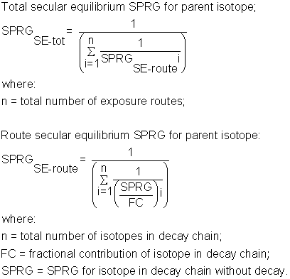
This is the preferred SPRG calculation option and is marked as the default selection in the calculator. When a single isotope is selected, the calculator identifies all the daughters in the chain. The SPRGs for each daughter are combined with the parent on a fractional basis. The fractional basis is determined by branching fractions where a progeny may decay into more than one isotope. The resulting SPRG is now based on secular equilibrium of the full chain. For straight chain decay, all the progeny would be at the same activity of the parent, and the SPRG provided in the output would be the inverse sum of the reciprocal SPRGs of the parent and all the progeny. Currently, all the soil SPRG equation images are presented with a radioactive decay term to account for half-lives shorter than the exposure duration. Decay is not included in this SPRG option because, under secular equilibrium, each isotope in the decay series is continuously replenished by the decay of its immediate predecessor — including the original progenitor — thereby maintaining a constant concentration for every member.
When the secular equilibrium SPRG output option is selected, the SPRG Calculator now gives the option to show the individual progeny contributions for the SPRG (and risk) output. When the option to display progeny contribution is selected, the SPRG Calculator output gives the secular equilibrium SPRG and the individual progeny SPRGs in separate tables.
A total SPRG is calculated using the following formula.
2.2.2 SPRG Output Option #2: Does Not Assume Secular Equilibrium, Provides Results for Progeny Throughout Chain (with decay where appropriate)
This option displays the SPRGs calculated with half-life decay as identified in the SPRG equation images. In addition to the selected isotope, all the individual progeny SPRGs are displayed. Each SPRG is determined with each isotope's respective half-life and not that of its parent isotope. This option does not assume secular equilibrium and presents all the individual progeny SPRGs, so that the risk assessor can identify isotopes that will be present and measure their activities. Users can alter progeny half-life to match the parent isotope or other progeny or to account for ingrowth and decay over a chain.
2.2.3 SPRG Output Option #3: Does Not Assume Secular Equilibrium, Selected Isotopes Only (with decay where appropriate)
This option displays SPRGs for only the selected isotopes, with half-life decay as identified in the SPRG equation images. In this output, secular equilibrium is not assumed, progeny SPRGs are not displayed, and progeny contribution is not combined into the SPRG for the selected isotope. This option is useful when contamination is from one radionuclide with a very long half-life, where secular equilibrium would be too conservative.
2.3 Slope Factors (SFs)
EPA classifies all radionuclides as Group A carcinogens ("carcinogenic to humans"). Group A classification is used only when there is sufficient evidence from epidemiologic studies to support a causal association between exposure to the agents and cancer. The appendix radionuclide table, from the Center for Radiation Protection Knowledge, lists ingestion, inhalation and external exposure cancer slope factors (risk coefficients for total cancer morbidity) for radionuclides in conventional units of picocuries (pCi). Ingestion and inhalation slope factors are central estimates in a linear model of the age-averaged, lifetime attributable radiation cancer incidence (fatal and nonfatal cancer) risk per unit of activity inhaled or ingested, expressed as risk/pCi. External exposure slope factors are central estimates of lifetime attributable radiation cancer incidence risk for each year of exposure to external radiation from photon-emitting radionuclides distributed uniformly in a thick layer of soil, expressed as risk/yr per pCi/gram soil. External exposure slope factors can also be used that have units of risk/yr per pCi/cm2 soil. When combined with site-specific media concentration data and appropriate exposure assumptions, slope factors can be used to estimate lifetime cancer risks to members of the general population due to radionuclide exposures. The slope factors are population-based risk metrics, expressing the probability of cancer occurrence in an exposed population, and are not predictive of cancer in any given individual. EPA currently provides guidance on inhalation risk assessment for chemicals in RAGS Part F (Risk Assessment Guidance for Superfund Volume I: Human Health Evaluation Manual, Part F, Supplemental Guidance for Inhalation Risk Assessment). The development of inhalation slope factors for radionuclides differs from the guidance presented in RAGS Part F.
The SFs from the Center for Radiation Protection Knowledge differ from the values presented in HEAST. The SFs were calculated using ORNL's DCAL software in the manner of Federal Guidance Report 12 and 13. For the calculation of soil ingestion slope factors, a standard soil density of 1.6 g/cm3 has been used. The radionuclides presented are those provided in the International Commission on Radiological Protection (ICRP) Publication 107. This document contains a revised database of nuclear decay data (energies and intensities of emitted radiations, physical half-lives and decay modes) for 1,252 naturally occurring and manmade radionuclides. ICRP Publication 107 supersedes the previous database, ICRP Publication 38, published in 1983.
Inhalation risk and dose coefficients for Rn-222, Rn-220, Bi-212, Bi-214, Pb-212, Pb-214, and Po-218 were updated in January 2017 and can be found here. The updated values are for inhalation of individual radionuclides without accompanying progeny but include the contribution to risk from ingrowth of radioactive progeny in the body following intake of a parent radionuclide. This approach allows the user to derive cancer risk and effective dose estimates for any known or hypothetical combination of Rn-222 or Rn-220 and its short-lived progeny in air. Rn-219 is not included in the update due to the large uncertainty in the distribution of decays of Rn-219 and its progeny in the body.
2.3.1 Metastable Isotopes
Most dose and risk coefficients are presented for radionuclides in their ground state. In the decay process, the newly formed nucleus may be in an excited state and emit radiation (e.g., gamma rays) to lose the energy of the state. The excited nucleus is said to be in a metastable state, which is denoted by the chemical symbol and atomic number appended by "m" (e.g., Ba-137m). If additional higher energy metastable states are present, then "n", "p", etc.... is appended. Metastable states have different physical half-lives and emit different radiations and thus unique dose and risk coefficients. In decay data tabulations of ICRP 107, if the half-life of a metastable state was less than 1 minute, then the radiations emitted in de-excitation are included with those of the parent radionuclide. Click to see a graphical representation of the decay of Cs-137 to Ba-137.
Eu-152, in addition to its ground state, has two metastable states: Eu-152m and Eu-152n. The half-lives of Eu-152, Eu-152m and Eu-152n are: 13.5 y, 9.31 m and 96 m, respectively, and the energy emitted per decay is 1.30 MeV, 0.080 MeV, and 0.14 MeV, respectively.
2.4 SPRG in Context of Superfund Modeling Framework
This recommended SPRG calculator focuses on the application of generic and simple site-specific approaches that are part of a larger framework for calculating concentration levels that are designed to be consistent with risk based criteria. Generic recommended SPRGs for a 1 × 10⁻⁶ cancer risk standard are provided by viewing either the tables in the Download Area section of this calculator or by running the SPRG Search section of this calculator with the "Get Default SPRGs" option.
Generic recommended SPRGs can be calculated from the same equations presented in the site-specific portion of the calculator, but typically they are based on a number of default assumptions chosen to be protective of human health for most site conditions. Generic recommended SPRGs can be used in place of site-specific SPRG levels; however, in general, they are expected to be more protective than site-specific levels. The site manager should weigh the cost of collecting the data necessary to develop site-specific SPRGs with the potential for deriving a higher SPRG that provides an appropriate level of protection.
To avoid unnecessary inconsistency between radiological and chemical risk assessment and radiological dose assessment at the same site, users should generally use the same model for chemical and radionuclide risk assessment and radionuclide dose assessment. If there is a reason on a site-specific basis for using another model, justification for doing so should be developed. The justification should include specific supporting data and information in the administrative record. The justification normally would include the model runs, using both the recommended EPA SPRG model and the alternative model. Users are cautioned that they should have a thorough understanding of both the SPRG recommended model and any alternative model when evaluating whether a different approach is appropriate. When alternative models are used, the user should adjust the default input parameters to be as close as possible to the SPRG inputs, which may be difficult since models tend to use different definitions for parameters. Numerous computerized mathematical models have been developed by EPA and other organizations to predict the fate and transport of radionuclides in the environment; these models include single-media unsaturated zone models (for example, groundwater transport) as well as multi-media models. These models have been designed for a variety of goals, objectives, and applications; as such, no single model may be appropriate for all site-specific conditions. Generally, even when a different model is used to predict fate and transport of radionuclides through different media, EPA recommends using the SPRG calculators for the remedial program to establish the risk-based concentrations to ensure consistency with CERCLA, the NCP, and EPA's Superfund guidance for remedial sites. Prior to using another model for risk assessment at a CERCLA remedial site, EPA regional staff should consult with the Superfund remedial program's National Radiation Expert (Stuart Walker, at (703) 603-8748 or walker.stuart@epa.gov). For more information on this issue, please see questions 10 and 16 on pages 12 and 17 to 18 of Radiation Risk Assessment At CERCLA Sites: Q & A (EPA 540-R-012-13, May 2014).
2.5 Understanding Risk Output on the SPRG Website
The SPRG calculator provides an option to select risk output. In the calculator, select "yes" if risk output is desired. Selecting risk output requires the calculator to be run in "Site Specific" mode. The risk values presented on this site are radionuclide-specific values for individual contaminants in dust, 2-D external exposure, and 3-D external exposure that may warrant further investigation or site cleanup.
2.5.1 General Considerations for the Risk Output
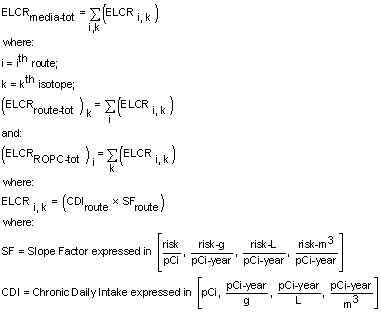
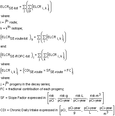
The first step in the risk assessment process is hazard identification where site data is screened against SPRGs to identify radionuclides of potential concern (ROPCs). The "Risk Characterization" step, in the risk assessment process, incorporates the outcome of the exposure and toxicity assessment steps to calculate the Excess Lifetime Cancer Risk (ELCR) identified in the data screening part of the hazard identification step. ELCR is calculated for each land use determined appropriate for the site. The ELCR sum is presented for each exposure route for all ROPCs and for each ROPC across all exposure routes. The process used to calculate ELCR in this calculator follows the traditional method of first calculating a CDI (Chronic Daily Intake).
The basic equation for calculating ELCR is:
The secular equilibrium equation for calculating ELCR is:
The risk results are color coded to identify risk ranges and radionuclides of concern (ROCs). The colors and the associated risk ranges are presented in the table below.
Excess Lifetime Cancer Risk Risk Range Risk < 0.000001 Risk > 0.000001 Risk > 0.0001 Color Code No shading Yellow Red 2.5.2 General Considerations for Entering Site Data
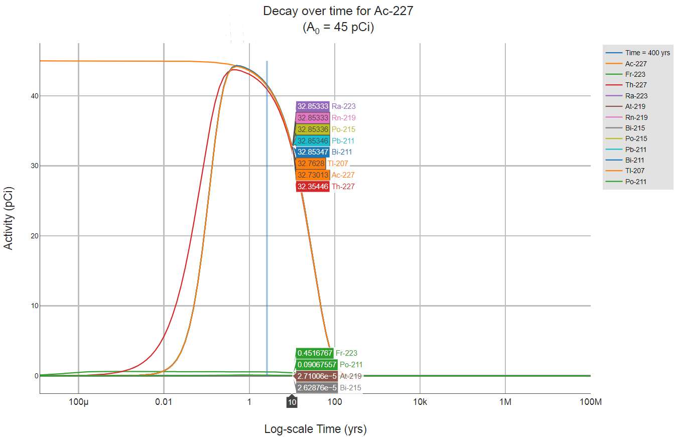
As presented in the previous section, the risk output is dependent on the SPRG calculated. Section 2.2 discusses the SPRG output options. To summarize section 2.2, the SPRG options are either secular equilibrium or not. If the data is collected from a site where secular equilibrium is assumed to be present, the user need only enter the activity of the parent in the calculator and a representative risk of the parent and all progeny will be presented in the calculator output. In the case of non-secular equilibrium, the current "state of the chain" may not be known or easily calculated. In the case of relatively fast decaying isotopes, significant decay or ingrowth of progeny may have occurred since the sample date. Further, determining future activity of the contaminants may be useful in planning for future release of a property.
A Decay Chain Activity Projection Tool has been developed where the user can select an isotope, enter a length of time to allow decay and ingrowth, and enter the beginning activity of the parent. The results of this tool, pictured below, are the activities of the parent and progeny at the end of the decay and ingrowth of progeny time. These activities can be entered into the SPRG calculator to calculate risk using the second and third SPRG Output options.
2.5.3 One-Hit Rule
The linear risk equation, listed above, is valid only at low risk levels (below estimated risks of 0.01). For sites where radiological exposure might be high (estimated risks above 0.01), the one-hit equation, which is consistent with the linear low-dose model, should be used instead (RAGS, part A, ch. 8). The results presented on the SPRG use this rule. In the following instances, the one-hit rule is used independently in the risk output tables:
Risk from a single exposure route for a single radionuclide. Summation of single radionuclide risk (without one-hit rule applied to single radionuclide results) for multiple exposure routes (right of each row). Summation of risk (without one-hit rule applied to single radionuclide results) from a single exposure route for multiple radionuclides (bottom of each column). Summation of total risk (without one-hit rule applied to single radionuclide results or summations listed above) from multiple radionuclides across multiple exposure routes (bottom right hand cell).
3. Understanding Your Superfund Site
The tables in the "SPRG Download Area" provide generic concentrations in the absence of site-specific exposure assessments. Screening concentrations can be used to:
- Prioritize multiple sites within a facility or exposure units
- Set risk-based detection limits for contaminants of potential concern (COPCs)
- Focus future risk assessment efforts
- Consider as risk-based cleanup levels, when appropriate for the site
3.1 Developing a Conceptual Site Model
When using SPRGs, the exposure pathways of concern and site conditions should match those of the screening levels. (Note, however, that future uses may not match current uses. Future uses of a site should be logical as conditions which might occur at the site in the future.) Thus, normally, a conceptual site model (CSM) should be developed to identify likely contaminant source areas, exposure pathways, and potential receptors. This information can be used to determine the applicability of screening levels at the site and the need for additional information. The final CSM should represent linkages among contaminant sources, release mechanisms, exposure pathways, and routes and receptors based on historical information. It summarizes the understanding of the contamination problem. A separate CSM for ecological receptors can be useful. Part 2 and Attachment A of the Soil Screening Guidance for Radionuclides: Users Guide (U.S. EPA 2000a) contains the recommended steps for developing a CSM
Existing EPA documents with additional CSM guidance are:
- Risk Assessment Guidance for Superfund: Volume I Human Health Evaluation Manual (Part D, Standardized Planning, Reporting, and Review of Superfund Risk Assessments). See Planning Table 1; and
- Soil Screening Guidance for Radionuclides: User's Guide. See Attachment A.
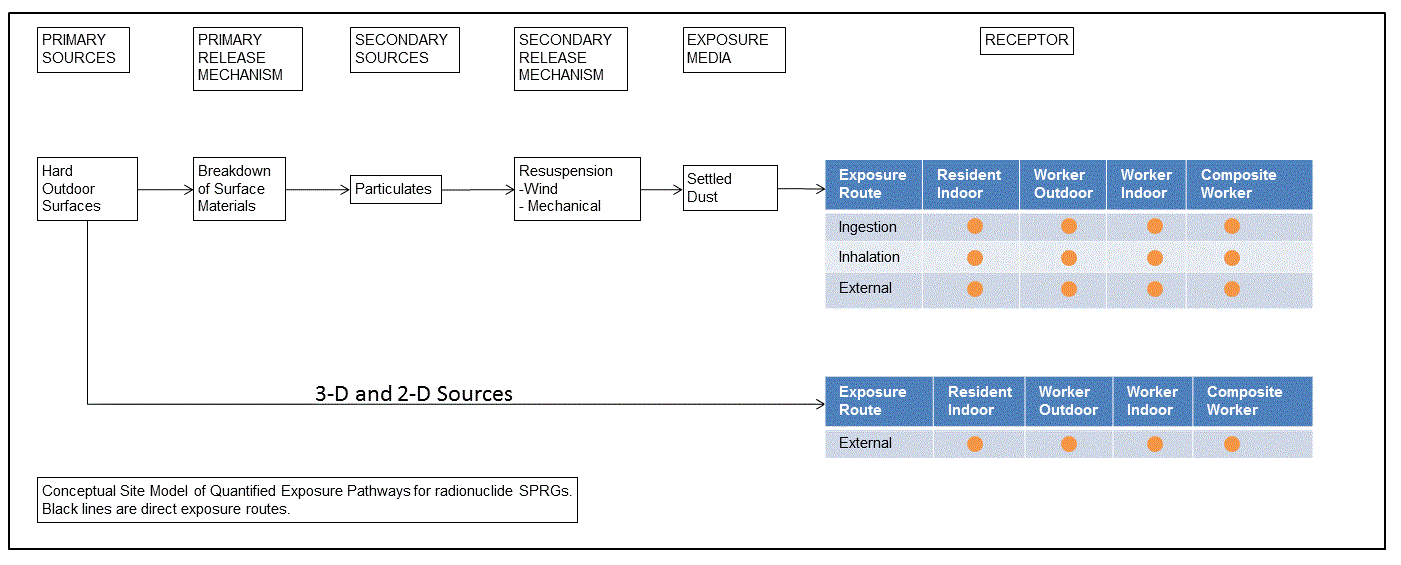
CSMs may be tabular, graphical, or stem-and-leaf. Section 4 of the user guide presents links to graphical CSMs for each scenario. Below is a stem-and-leaf CSM showing the exposure routes quantified and not quantified in this calculator.
As a final check, the CSM should answer the following questions:
- Are there potential ecological concerns?
- Is there potential for land use other than those listed in the SPRG calculator (e.g., recreational, agricultural or trespasser)?
- Are there other likely human exposure pathways that were not considered in development of the recommended SPRG levels?
- Are there unusual site conditions (e.g. large areas of contamination, high fugitive dust levels, potential for indoor air contamination)?
The recommended SPRGs may need to be adjusted to reflect the answers to these questions, and additional tools or assessment methodologies may need to be considered (e.g., if there may be potentially significant ecological risk). The recommended default scenarios in this calculator are based on the same default scenarios EPA provides in its guidance. Other scenarios may be investigated, using the SPRG calculator, by altering recommended site-specific exposure parameters.
3.2 Background Radiation
Natural background radiation should be considered prior to applying SPRGs as cleanup levels. Background and site-related levels of radiation should be addressed as they are for other contaminants at CERCLA sites. For further information, see EPA's guidance "Role of Background in the CERCLA Cleanup Program", April 2002 (OSWER 9285.6-07P). It should be noted that certain ARARs specifically address how to factor background into cleanup levels. For example, some radiation ARAR levels are established as increments above background concentrations. In these circumstances, background should be addressed in the manner prescribed by the ARAR. Additional information on radioactive materials present in building materials can be found in Volume 105, Number 2, March-April 2000, Journal of Research of the National Institute of Standards and Technology, Radioactivity Measurements on Glazed Ceramic Surfaces.
3.3 Potential Problems and Limitations
As with any risk-based tool, the potential exists for misapplication. In most cases, this results from not understanding the intended use of the recommended SPRGs. In order to prevent misuse of the recommended SPRGs, floow these guidelines:
- Do not apply recommended SPRG levels to a site without adequately developing a conceptual site model that identifies relevant exposure pathways and exposure scenarios.
- Do not use recommended SPRG levels as cleanup levels without the consideration of other relevant criteria, such as ARARs.
- Do not use recommended SPRG levels as cleanup levels without verifying numbers with a health physicist/risk assessor.
- Do not use outdated SPRG tables that have been superseded by more recent publications.
- Make sure to consider the effects from the presence of multiple isotopes.
4. Land Use Descriptions, Equations, and Technical Documentation
The recommended SPRGs consider human exposure from direct contact with contaminated outdoor dust on solid surfaces and external exposure to contaminated streets, sidewalks, finite slabs and building materials. The equations and technical discussion are aimed at developing concentration levels for risk-based SPRGs. The following text presents the recommended land use equations and their exposure routes. Table 1 presents the suggested definitions of the variables and their default values. Any alternative values or assumptions used in remedy evaluation or selection on a CERCLA site should be presented with supporting rationale in the Administrative Record.
For a graphical representation and brief description of the routes of exposure for each exposure scenario, click on the name of the exposure scenarios below:
4.1 Resident
Exposure to Settled Dust on Outdoor Surfaces
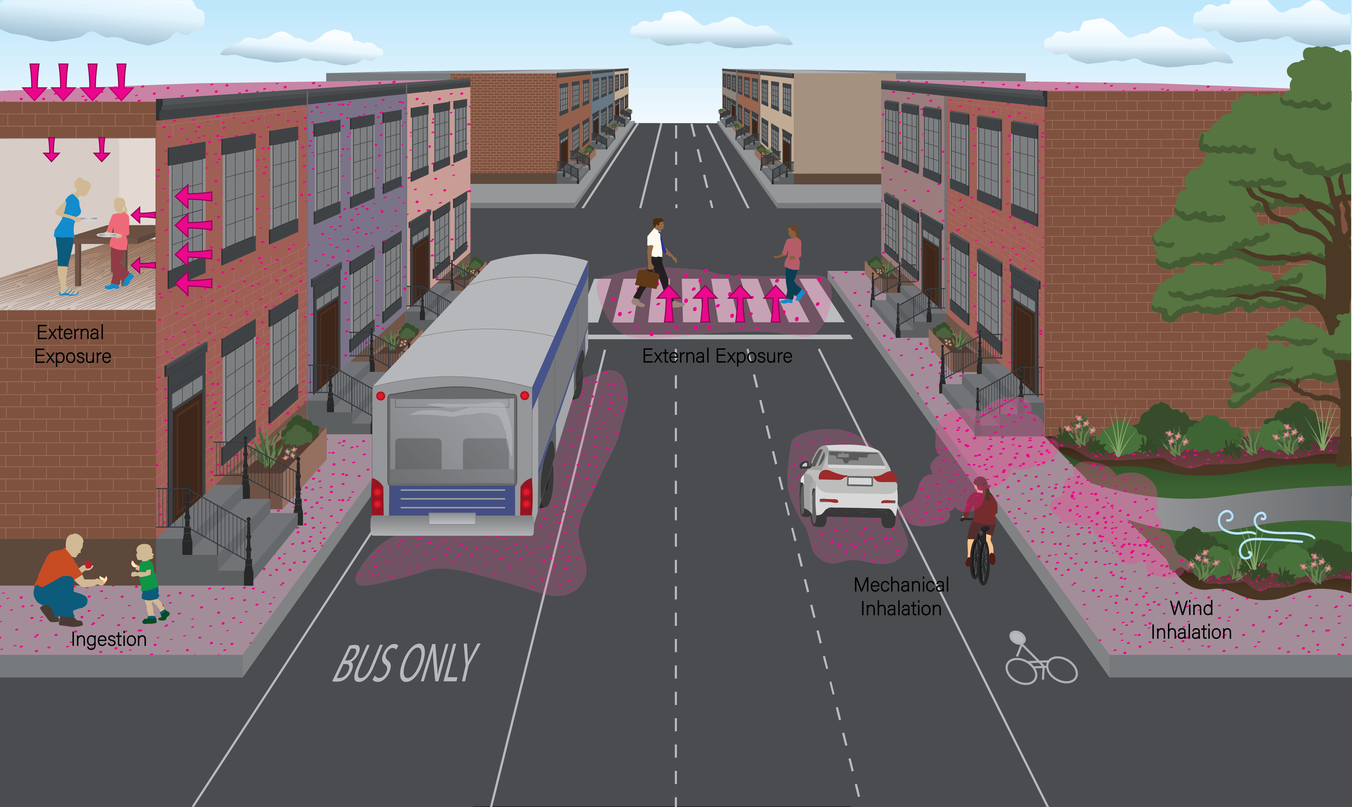
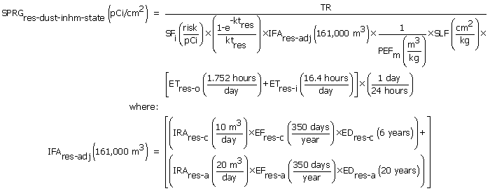
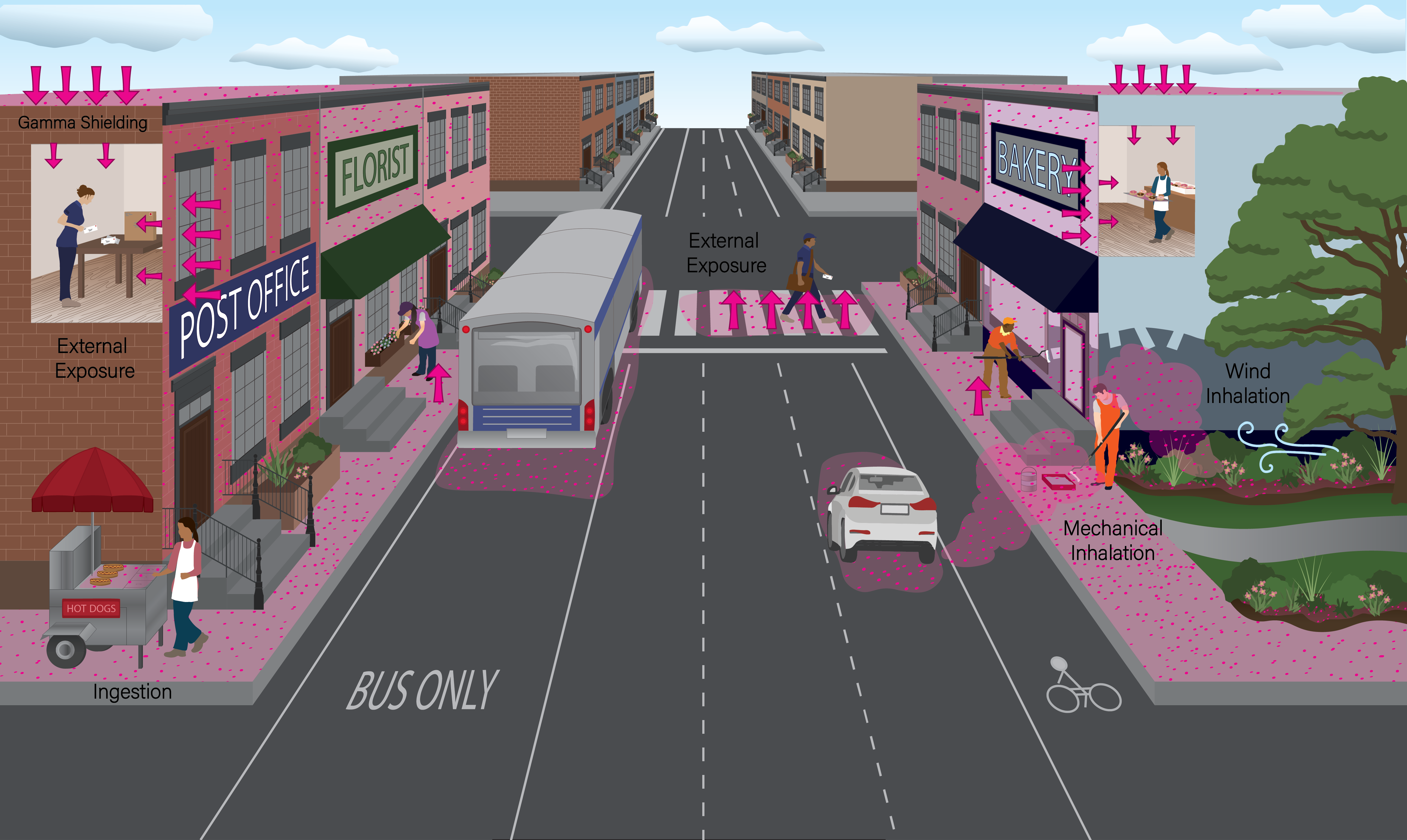
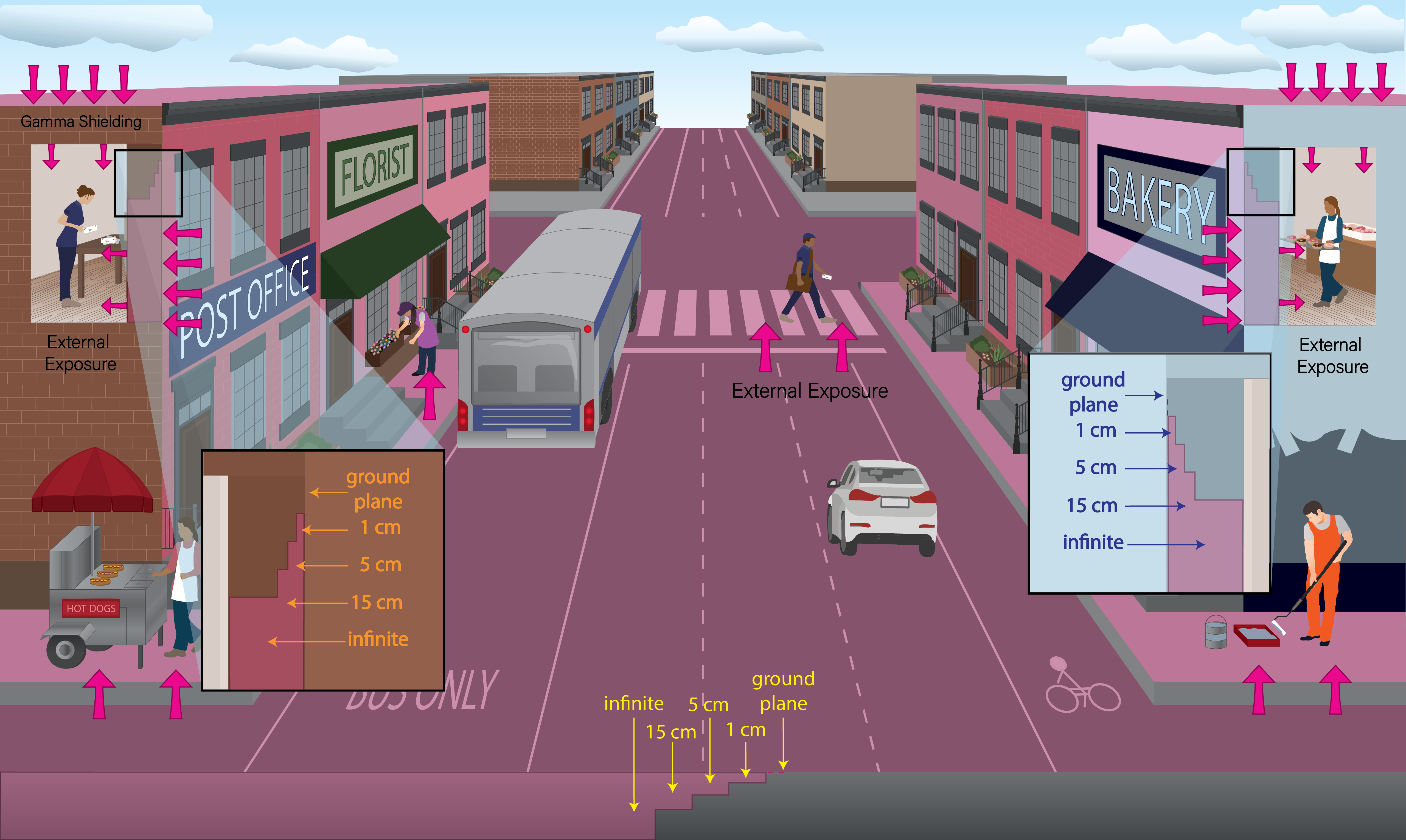
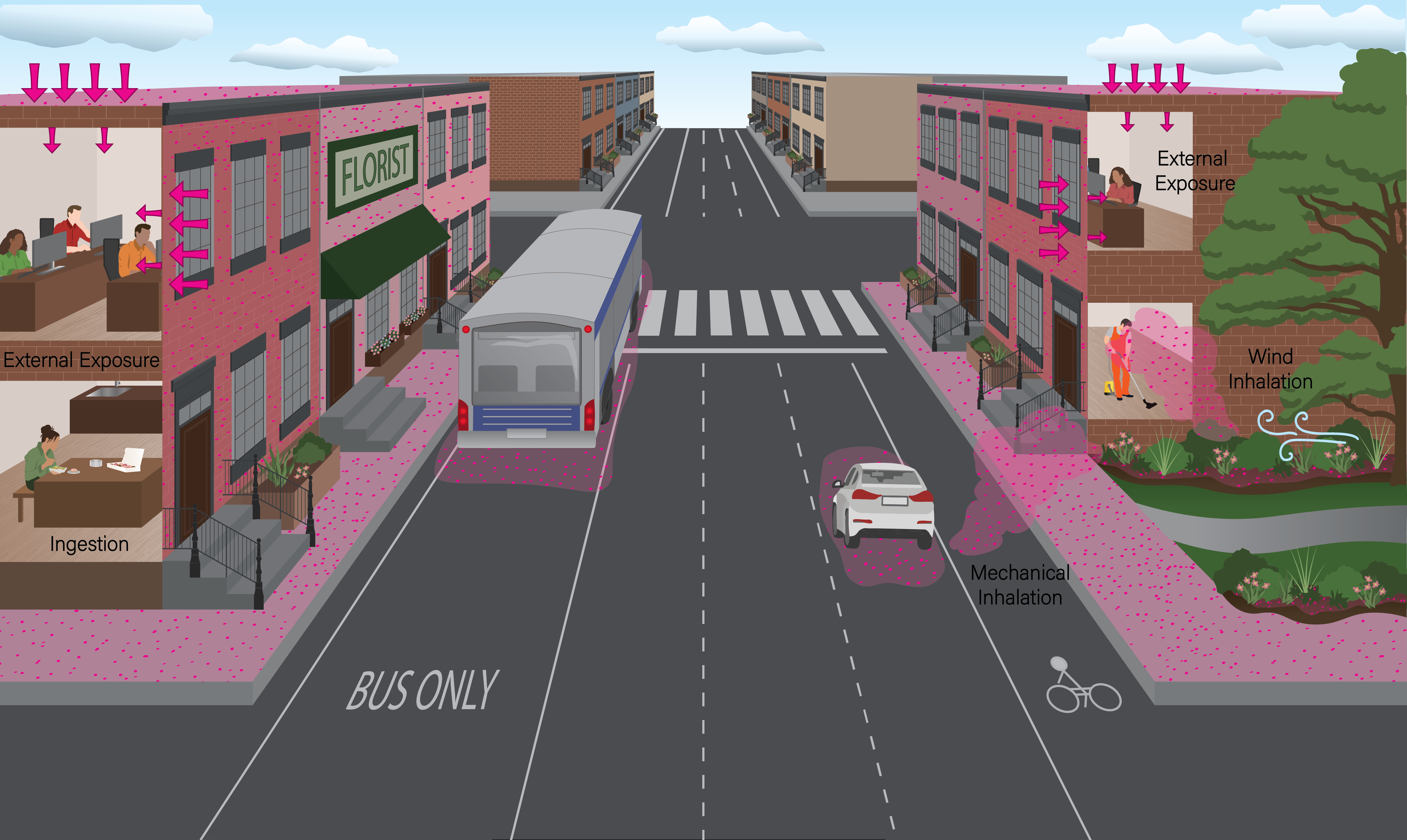
The resident is exposed to contaminated dust settled on outdoor surfaces. The resident spends some time inside and some time outside. Three exposure routes are presented: (1) exposure to contamination deposited on surfaces via incidental ingestion, (2) inhalation of resuspended particulates, and (3) external exposure to ionizing radiation from dust settled on contaminated surfaces. For the portion of the time that the resident is indoors, this equation includes an indoor air dilution factor for inhalation and a gamma shielding factor for external exposure.
SPRG Equations
These scenarios evaluate age-adjusted incidental ingestion, age-adjusted inhalation of particulates, and external exposure to ionizing radiation from settled dust using ground plane toxicity values.
Ingestion
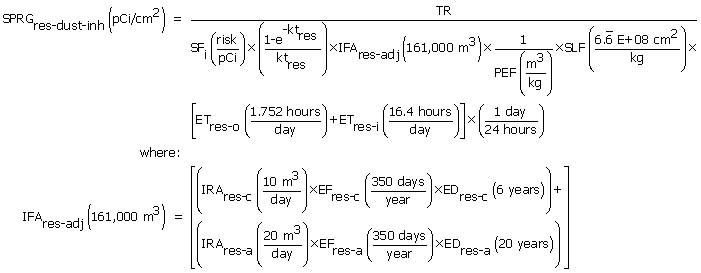
Inhalation with PEF wind
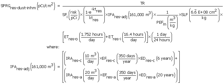
Inhalation with PEF mechanical
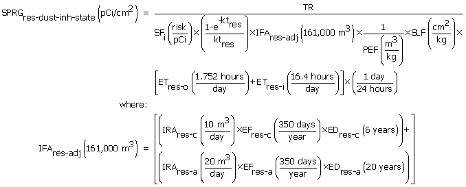
Inhalation with PEF wind for State-Specific
Inhalation with PEF mechanical for State-Specific
External
Total
Definitions of the input variables are in Table 1.
CDI Equations
These scenarios evaluate age-adjusted incidental ingestion, age-adjusted inhalation of particulates, and external exposure to ionizing radiation from settled dust using ground plane toxicity values.
Ingestion
Inhalation with PEF wind
Inhalation with PEF mechanical
Inhalation with PEF wind for State-Specific
Inhalation with PEF mechanical for State-Specific
External
Definitions of the input variables are in Table 1.
3-D External Exposure to Dust on Outdoor Surfaces
Graphical Representations
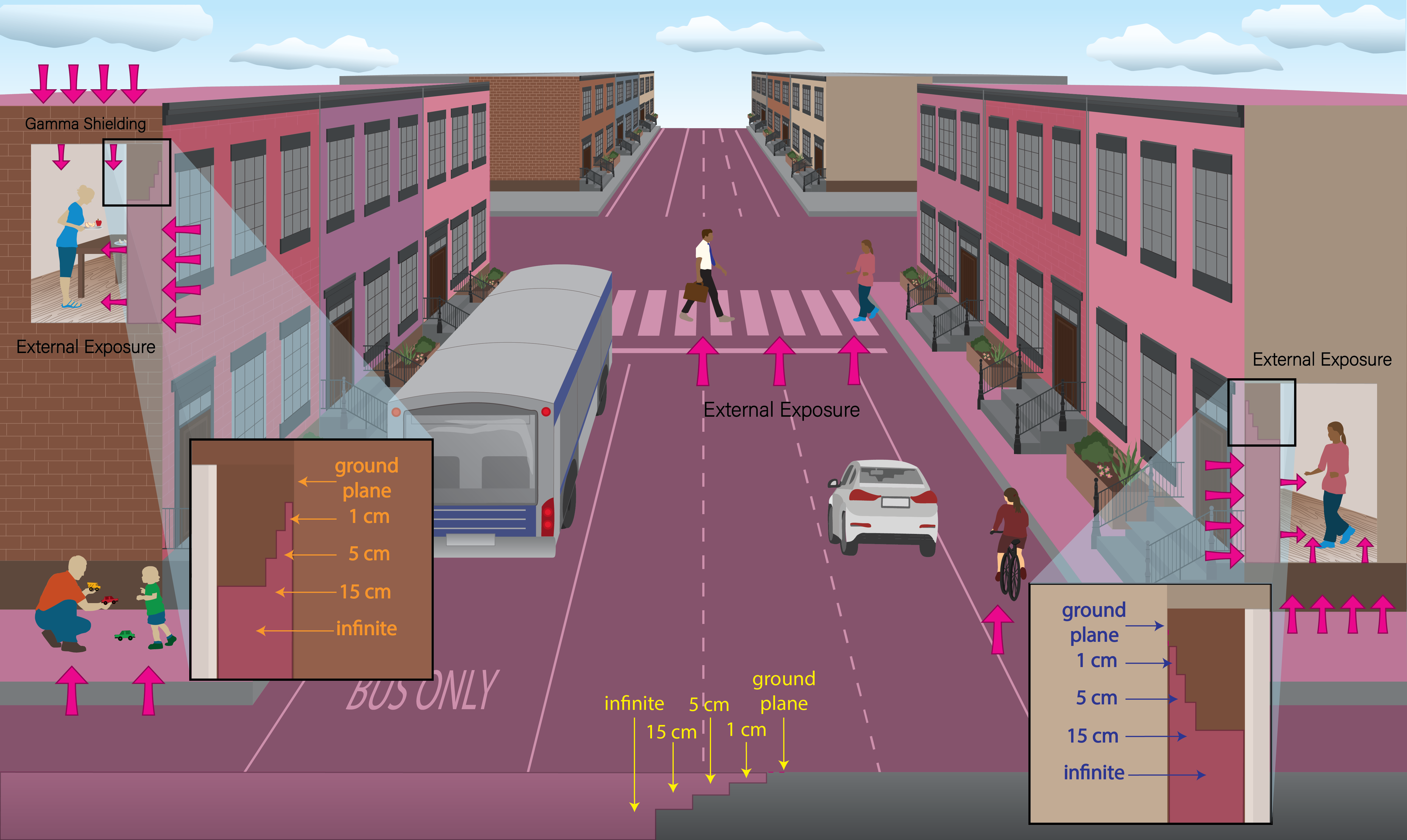
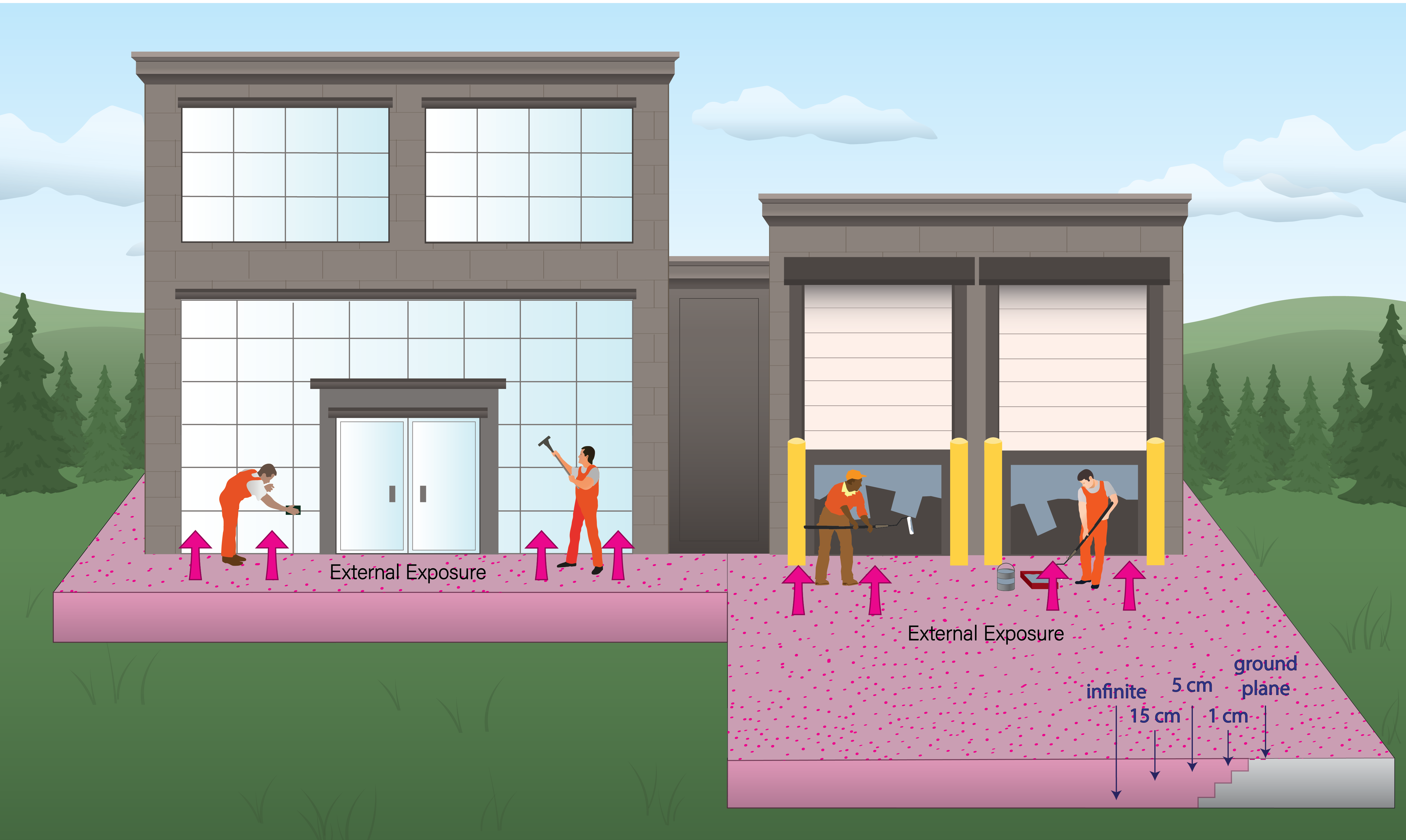
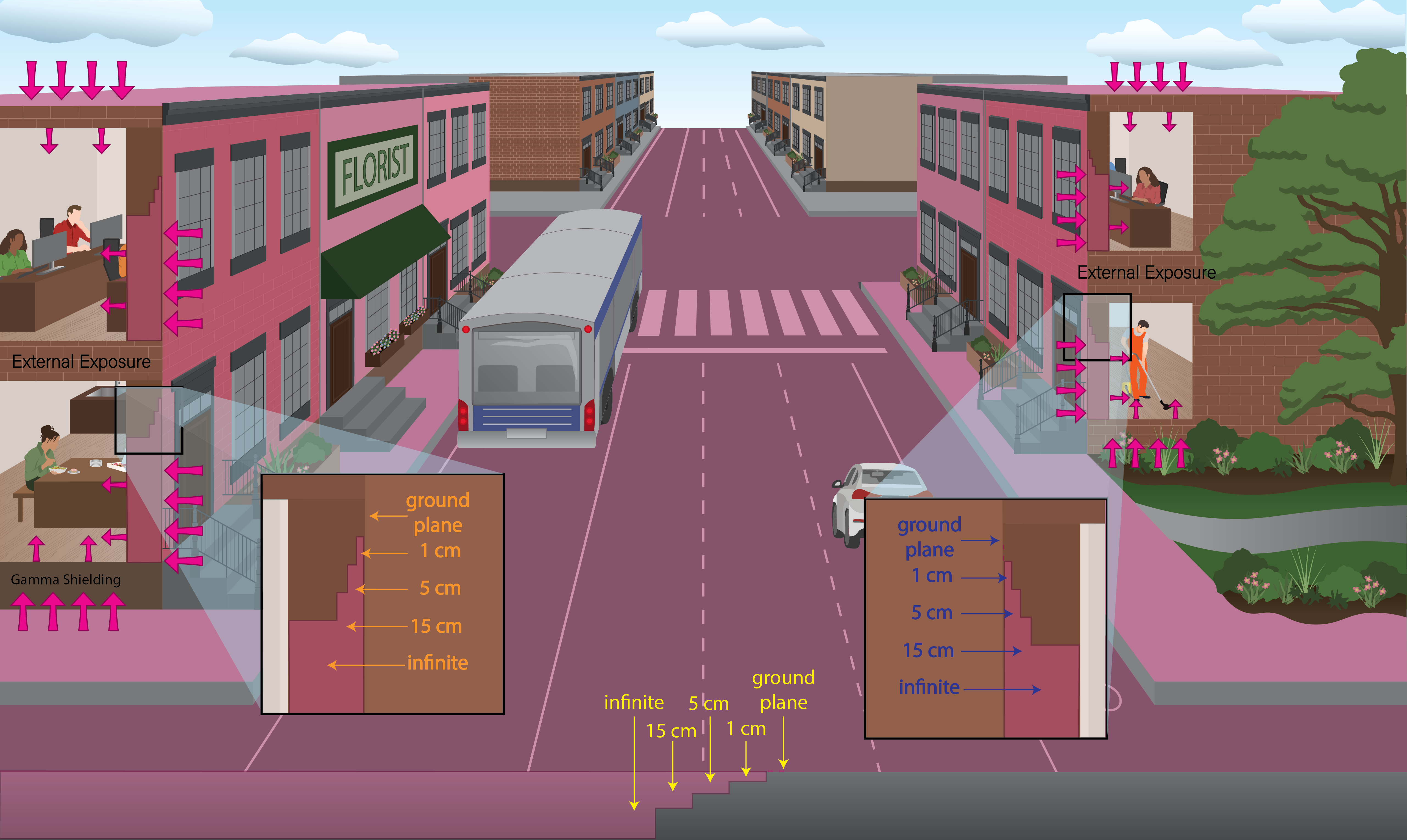
The resident is exposed to gamma radiation on outdoor surfaces. The only pathway considered is external exposure to ionizing radiation. It is assumed that the street (horizontal) and the building walls (vertical) on both sides of the street are radioactively contaminated.
SPRG Equations
This scenario evaluates fixed contaminated dust on surface of outside walls, streets, and sidewalks using ground plane toxicity values.
Contaminated building materials using ground plane external exposure toxicity values
These scenarios evaluate fixed contaminated dust on building materials of outside walls, streets, and sidewalks using various soil volume toxicity values.
Contaminated building materials using 1 cm soil volume toxicity values
Contaminated building materials using 5 cm soil volume toxicity values
Contaminated building materials using 15 cm soil volume toxicity values
Contaminated building materials using infinite soil volume toxicity values
Definitions of the input variables are in Table 1.
CDI Equations
This scenario evaluates fixed contaminated dust on surface of outside walls, streets, and sidewalks using ground plane toxicity values.
Contaminated building materials using ground plane external exposure toxicity values
These scenarios evaluate fixed contaminated dust on building materials of outside walls, streets, and sidewalks using various soil volume toxicity values.
Contaminated building materials using 1 cm soil volume toxicity values
Contaminated building materials using 5 cm soil volume toxicity values
Contaminated building materials using 15 cm soil volume toxicity values
Contaminated building materials using infinite soil volume toxicity values
Definitions of the input variables are in Table 1.
2-D External Exposure to Dust on Outdoor Surfaces
Graphical Representations
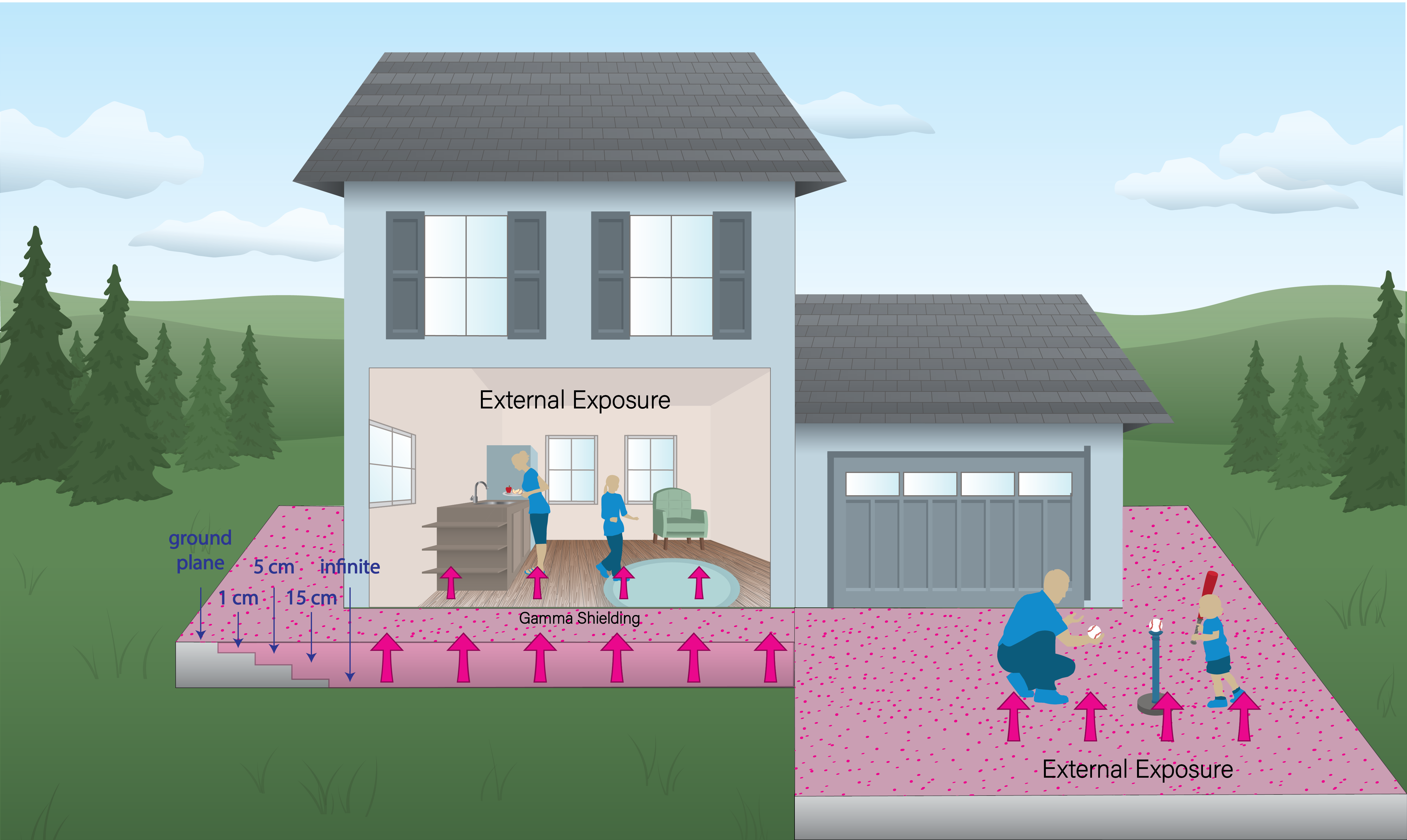
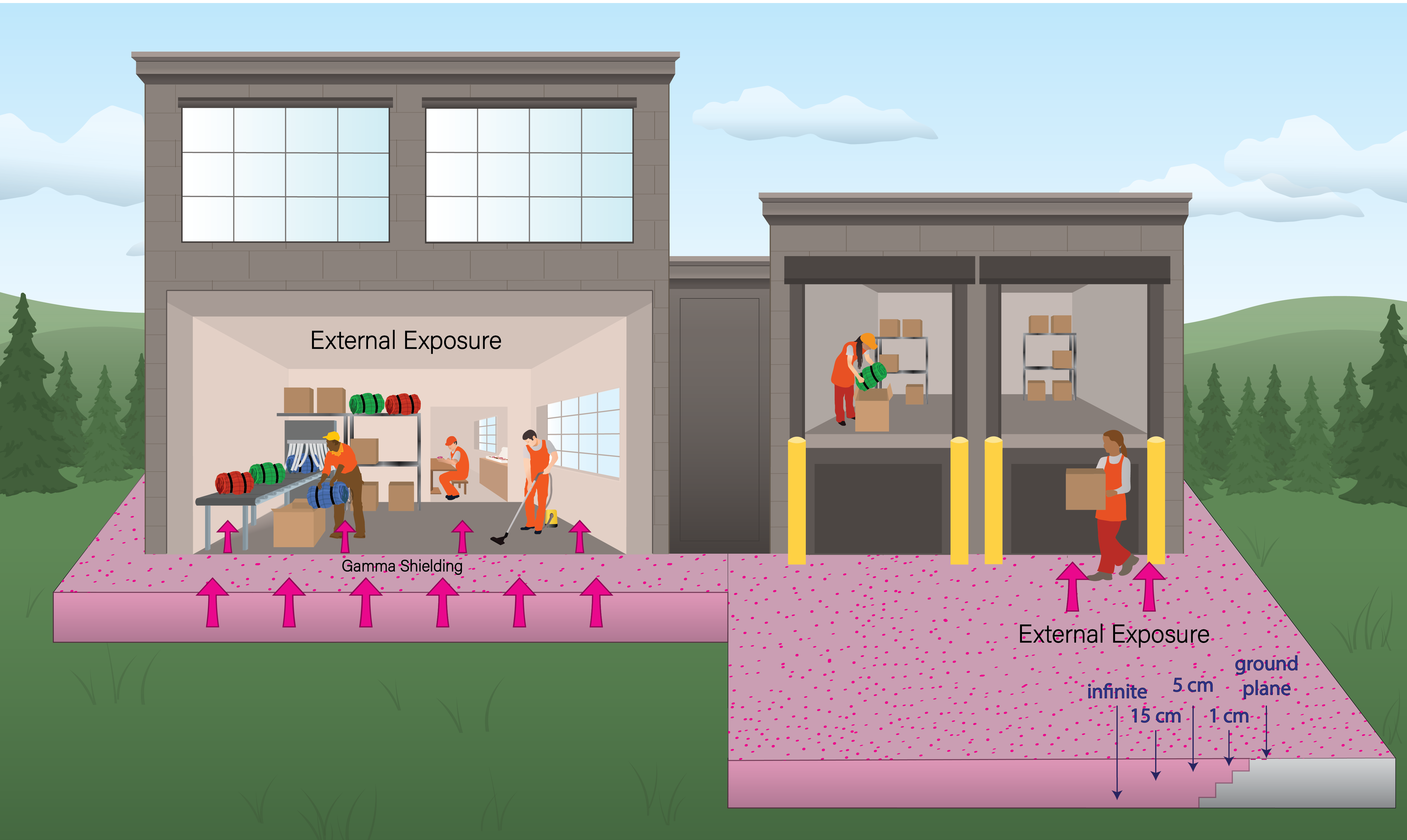
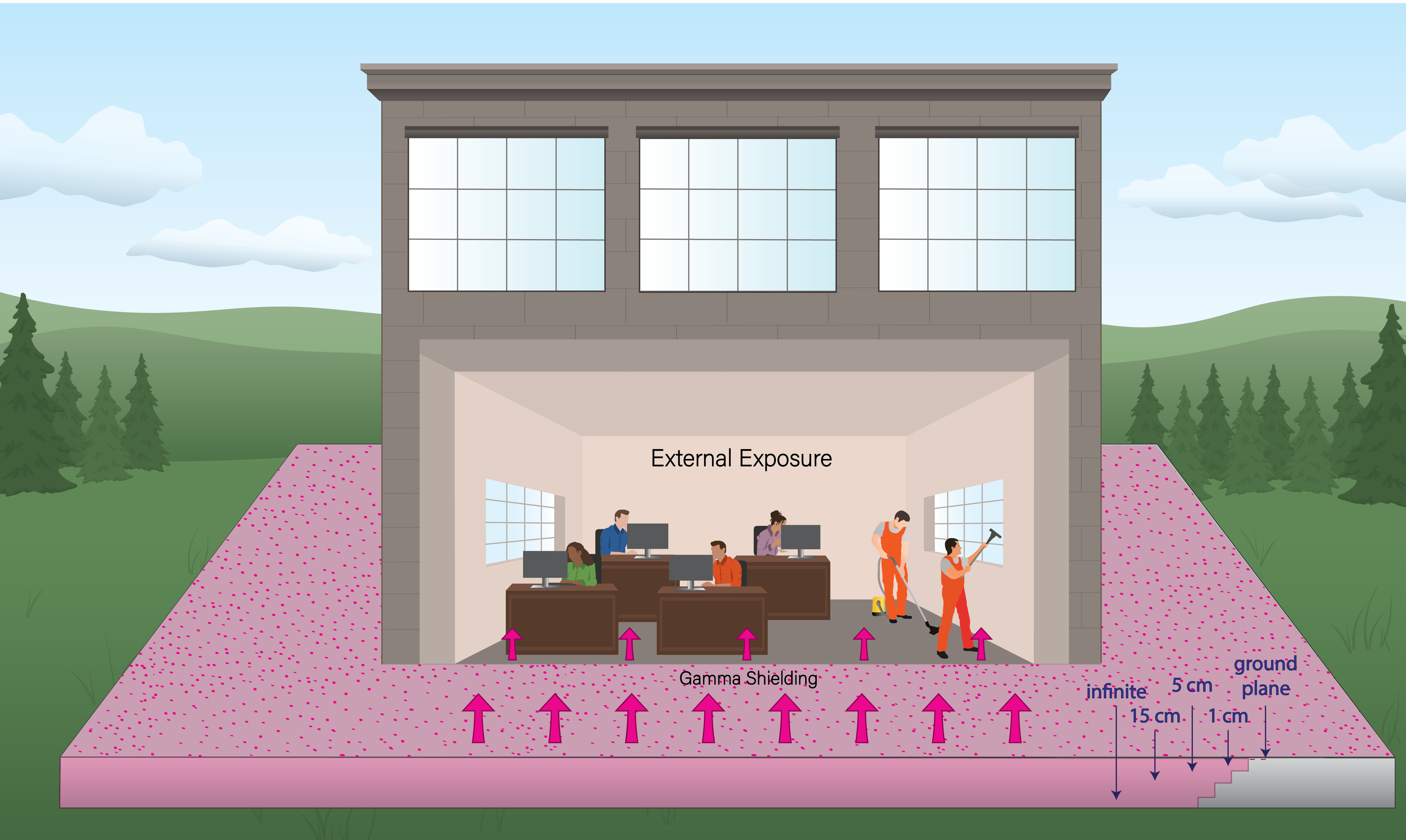
The resident is exposed to gamma radiation from settled dust on finite slabs. The only pathway considered is external exposure to ionizing radiation. It is assumed that the dust on the finite slab (horizontal) is radioactively contaminated. It is also assumed the resident lives in a structure built on top of the middle of the slab.
SPRG Equations
This scenario evaluates fixed contaminated dust on surfaces of outside streets and sidewalks using ground plane toxicity values.
Contaminated building materials using ground plane toxicity values
These scenarios evaluate contaminated building materials of streets and sidewalks using various soil volume toxicity values.
Contaminated building materials using 1 cm soil volume toxicity values
Contaminated building materials using 5 cm soil volume toxicity values
Contaminated building materials using 15 cm soil volume toxicity values
Contaminated building materials using infinite soil volume toxicity values
Definitions of the input variables are in Table 1.
CDI Equations
This scenario evaluates fixed contaminated dust on surfaces of outside streets and sidewalks using ground plane toxicity values.
Contaminated building materials using ground plane toxicity values
These scenarios evaluate contaminated building materials of streets and sidewalks using various soil volume toxicity values.
Contaminated building materials using 1 cm soil volume toxicity values
Contaminated building materials using 5 cm soil volume toxicity values
Contaminated building materials using 15 cm soil volume toxicity values
Contaminated building materials using infinite soil volume toxicity values
Definitions of the input variables are in Table 1.
4.2 Composite Worker
Exposure to Settled Dust on Outdoor Surfaces
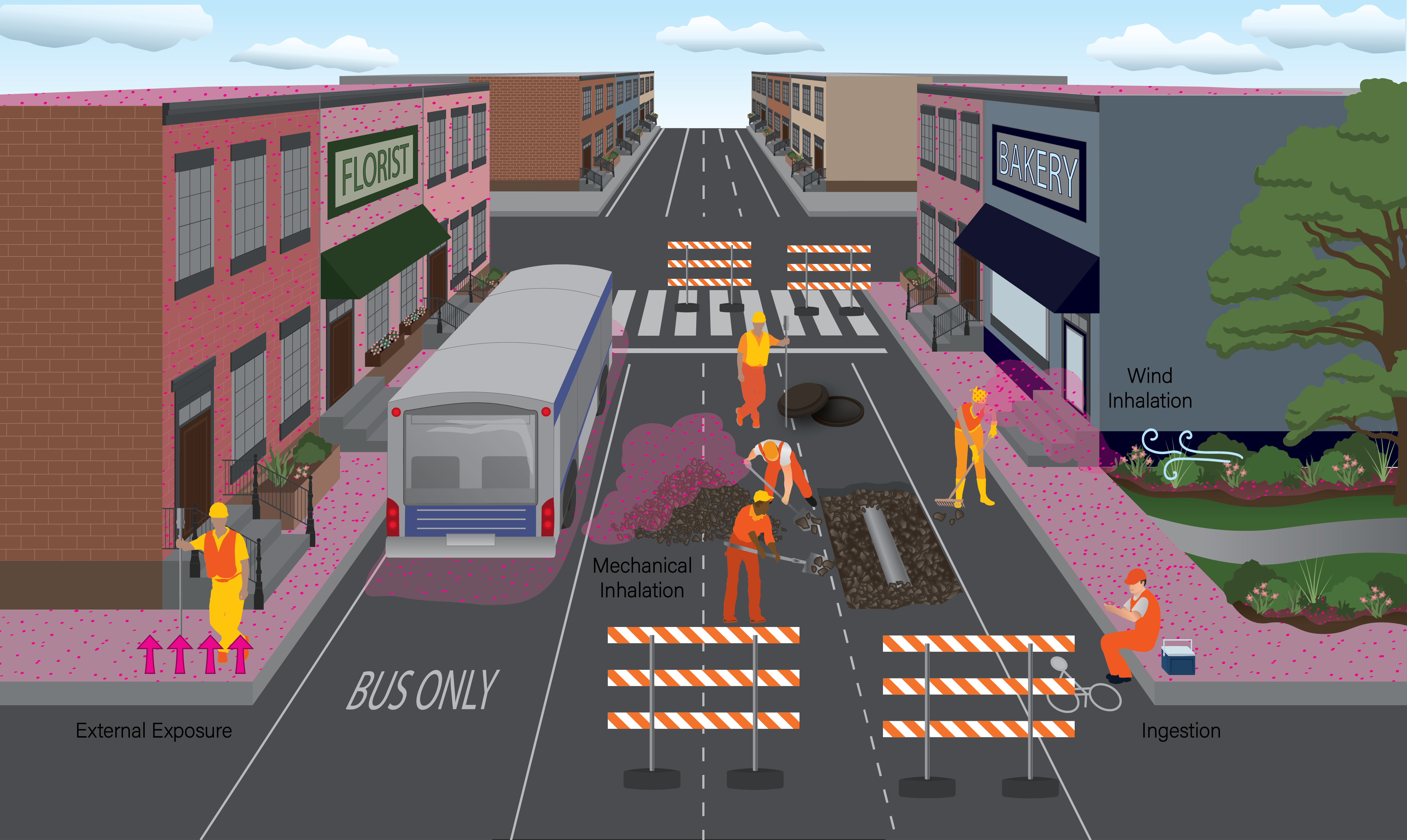
The composite worker is comprised of the most protective exposure parameters from the indoor and outdoor worker land uses. Three exposure routes are presented: (1) exposure to contamination deposited on surfaces via incidental ingestion, (2) inhalation of particulates, and (3) external exposure to ionizing radiation from dust settled on contaminated surfaces.
SPRG Equations
These scenarios evaluate incidental ingestion, inhalation of particulates, and external exposure to ionizing radiation from settled dust using ground plane toxicity values.
Ingestion
Inhalation with PEF wind
Inhalation with PEF mechanical
Inhalation with PEF wind for State-Specific
Inhalation with PEF mechanical for State-Specific
External
Total
Definitions of the input variables are in Table 1.
CDI Equations
These scenarios evaluate incidental ingestion, inhalation of particulates, and external exposure to ionizing radiation from settled dust using ground plane toxicity values.
Ingestion
Inhalation with PEF wind
Inhalation with PEF mechanical
Inhalation with PEF wind for State-Specific
Inhalation with PEF mechanical for State-Specific
External
Definitions of the input variables are in Table 1.
3-D External Exposure to Dust on Outdoor Surfaces
Graphical Representations
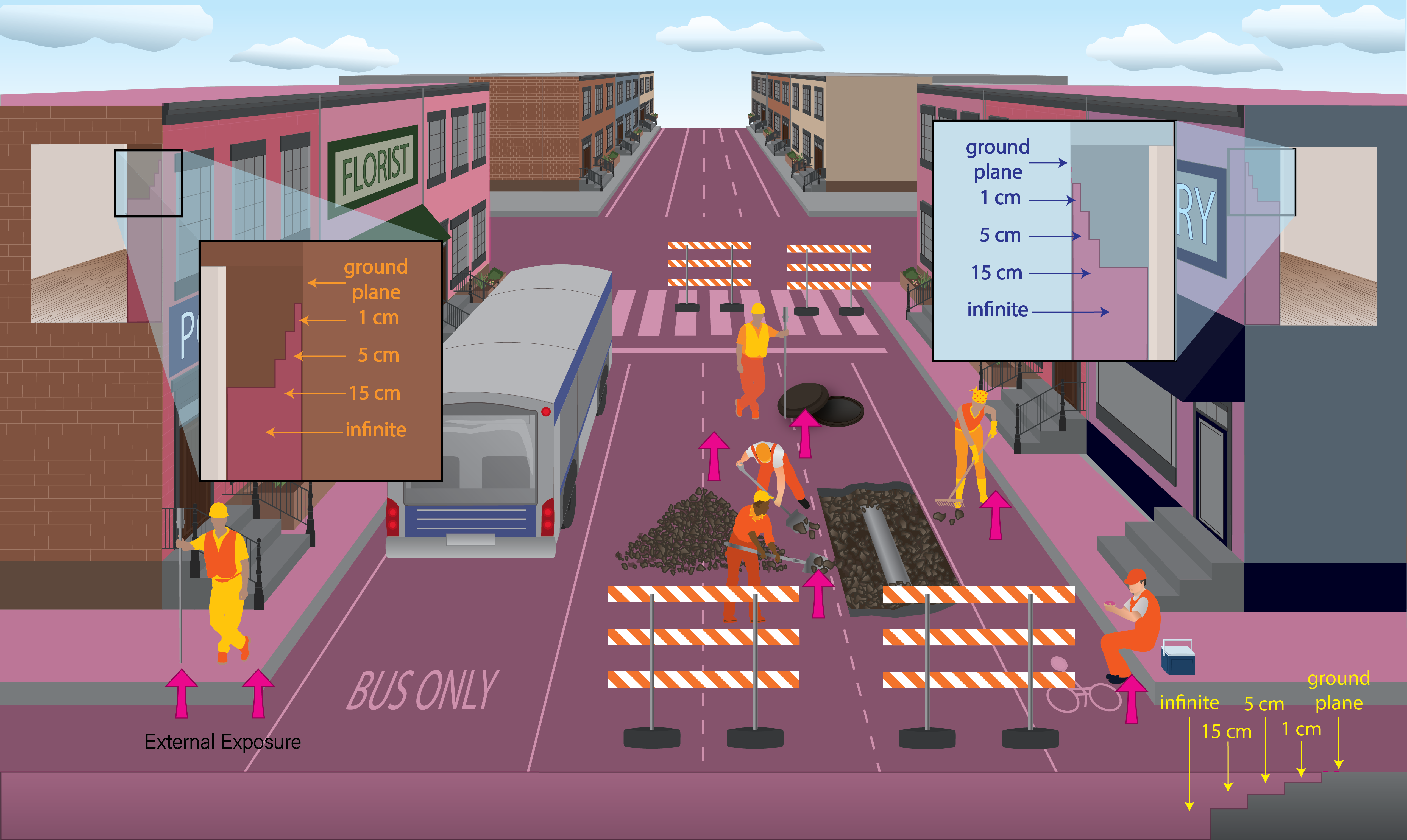
The composite worker is exposed to settled dust on outdoor surfaces. The only pathway considered is external exposure to ionizing radiation. It is assumed that the street (horizontal) and the building walls (vertical) on both sides of the street are contaminated with settled dust.
SPRG Equations
This scenario evaluates fixed contaminated dust on surface of outside walls, streets, and sidewalks using ground plane toxicity values
Contaminated building materials using ground plane external exposure toxicity values
These scenarios evaluate fixed contaminated dust on building materials of outside walls, streets, and sidewalks using various soil volume toxicity values.
Contaminated building materials using 1 cm soil volume toxicity values
Contaminated building materials using 5 cm soil volume toxicity values
Contaminated building materials using 15 cm soil volume toxicity values
Contaminated building materials using infinite soil volume toxicity values
Definitions of the input variables are in Table 1.
CDI Equations
This scenario evaluates fixed contaminated dust on surface of outside walls, streets, and sidewalks using ground plane toxicity values
Contaminated building materials using ground plane external exposure toxicity values
These scenarios evaluate fixed contaminated dust on building materials of outside walls, streets, and sidewalks using various soil volume toxicity values.
Contaminated building materials using 1 cm soil volume toxicity values
Contaminated building materials using 5 cm soil volume toxicity values
Contaminated building materials using 15 cm soil volume toxicity values
Contaminated building materials using infinite soil volume toxicity values
Definitions of the input variables are in Table 1.
2-D External Exposure to Dust on Outdoor Surfaces
Graphical Representations
The composite worker is exposed to settled dust on finite slabs. The only pathway considered is external exposure to ionizing radiation. It is assumed that the dust on the finite slab (horizontal) is radioactively contaminated.
SPRG Equations
This scenario evaluates fixed contaminated dust on surfaces of outside streets and sidewalks using ground plane toxicity values.
These scenarios evaluate contaminated building materials of streets and sidewalks using various soil volume toxicity values.
Contaminated building materials using 1 cm soil volume toxicity values
Contaminated building materials using 5 cm soil volume toxicity values
Contaminated building materials using 15 cm soil volume toxicity values
Contaminated building materials using infinite soil volume toxicity values
Definitions of the input variables are in Table 1.
CDI Equations
This scenario evaluates fixed contaminated dust on surfaces of outside streets and sidewalks using ground plane toxicity values.
These scenarios evaluate contaminated building materials of streets and sidewalks using various soil volume toxicity values.
Contaminated building materials using 1 cm soil volume toxicity values
Contaminated building materials using 5 cm soil volume toxicity values
Contaminated building materials using 15 cm soil volume toxicity values
Contaminated building materials using infinite soil volume toxicity values
Definitions of the input variables are in Table 1.
4.3 Outdoor Worker
Exposure to Settled Dust on Outdoor Surfaces
The outdoor worker is exposed to contaminated dust settled on outdoor surfaces. The outdoor worker spends his entire shift outside. Three exposure routes are presented: (1) exposure to contamination deposited on surfaces via incidental ingestion, (2) inhalation of particulates, and (3) external exposure to ionizing radiation from dust settled on contaminated surfaces.
SPRG Equations
These scenarios evaluate incidental ingestion, inhalation of particulates, and external exposure to ionizing radiation from settled dust using ground plane toxicity values.
Ingestion
Inhalation with PEF wind
Inhalation with PEF mechanical
Inhalation with PEF wind for State-Specific
Inhalation with PEF mechanical for State-Specific
External
Total
Definitions of the input variables are in Table 1.
CDI Equations
These scenarios evaluate incidental ingestion, inhalation of particulates, and external exposure to ionizing radiation from settled dust using ground plane toxicity values.
Ingestion
Inhalation with PEF wind
Inhalation with PEF mechanical
Inhalation with PEF wind for State-Specific
Inhalation with PEF mechanical for State-Specific
External
Definitions of the input variables are in Table 1.
3-D External Exposure to Dust on Outdoor Surfaces
Graphical Representations
The outdoor worker is exposed to settled dust on outdoor surfaces. The only pathway considered is external exposure to ionizing radiation. It is assumed that the street (horizontal) and the building walls (vertical) on both sides of the street are contaminated with settled dust.
SPRG Equations
This scenario evaluates fixed contaminated dust on surface of outside walls, streets, and sidewalks using ground plane toxicity values.
Contaminated building materials using ground plane external exposure toxicity values
These scenarios evaluate fixed contaminated dust on building materials of outside walls, streets, and sidewalks using various soil volume toxicity values.
Contaminated building materials using 1 cm soil volume toxicity values
Contaminated building materials using 5 cm soil volume toxicity values
Contaminated building materials using 15 cm soil volume toxicity values
Contaminated building materials using infinite soil volume toxicity values
Definitions of the input variables are in Table 1.
CDI Equations
This scenario evaluates fixed contaminated dust on surface of outside walls, streets, and sidewalks using ground plane toxicity values.
Contaminated building materials using ground plane external exposure toxicity values
These scenarios evaluate fixed contaminated dust on building materials of outside walls, streets, and sidewalks using various soil volume toxicity values.
Contaminated building materials using 1 cm soil volume toxicity values
Contaminated building materials using 5 cm soil volume toxicity values
Contaminated building materials using 15 cm soil volume toxicity values
Contaminated building materials using infinite soil volume toxicity values
Definitions of the input variables are in Table 1.
2-D External Exposure to Dust on Outdoor Surface
Graphical Representations
The outdoor worker is exposed to settled dust on finite slabs. The only pathway considered is external exposure to ionizing radiation. It is assumed that the dust on the finite slab (horizontal) is radioactively contaminated.
SPRG Equations
This scenario evaluates fixed contaminated dust on surfaces of outside streets and sidewalks using ground plane toxicity values.
Contaminated building materials using ground plane external exposure toxicity values
These scenarios evaluate contaminated building materials of streets and sidewalks using various soil volume toxicity values.
Contaminated building materials using 1 cm soil volume toxicity values
Contaminated building materials using 5 cm soil volume toxicity values
Contaminated building materials using 15 cm soil volume toxicity values
Contaminated building materials using infinite soil volume toxicity values
Definitions of the input variables are in Table 1.
CDI Equations
This scenario evaluates fixed contaminated dust on surfaces of outside streets and sidewalks using ground plane toxicity values.
Contaminated building materials using ground plane external exposure toxicity values
These scenarios evaluate contaminated building materials of streets and sidewalks using various soil volume toxicity values.
Contaminated building materials using 1 cm soil volume toxicity values
Contaminated building materials using 5 cm soil volume toxicity values
Contaminated building materials using 15 cm soil volume toxicity values
Contaminated building materials using infinite soil volume toxicity values
Definitions of the input variables are in Table 1.
4.4 Indoor Worker
Exposure to Settled Dust on Outdoor Surfaces
SPRG Equations
These scenarios evaluate incidental ingestion, inhalation of particulates, and external exposure to ionizing radiation from settled dust using ground plane toxicity values.
Ingestion
Inhalation with PEF wind
Inhalation with PEF mechanical
Inhalation with PEF wind for State-Specific
Inhalation with PEF mechanical for State-Specific
External
Total
Definitions of the input variables are in Table 1.
CDI Equations
These scenarios evaluate incidental ingestion, inhalation of particulates, and external exposure to ionizing radiation from settled dust using ground plane toxicity values.
Ingestion
Inhalation with PEF wind
Inhalation with PEF mechanical
Inhalation with PEF wind for State-Specific
Inhalation with PEF mechanical for State-Specific
External
Definitions of the input variables are in Table 1.
3-D External Exposure to Dust on Outdoor Surfaces
Graphical Representations
The outdoor worker is exposed to settled dust on outdoor surfaces. The only pathway considered is external exposure to ionizing radiation. It is assumed that the street (horizontal) and the building walls (vertical) on both sides of the street are contaminated with settled dust.
SPRG Equations
This scenario evaluates fixed contaminated dust on surface of outside walls, streets, and sidewalks using ground plane toxicity values.
Contaminated building materials using ground plane external exposure toxicity values
These scenarios evaluate contamination on building materials of outside walls, streets, and sidewalks using various soil volume toxicity values.
Contaminated building materials using 1 cm soil volume toxicity values
Contaminated building materials using 5 cm soil volume toxicity values
Contaminated building materials using 15 cm soil volume toxicity values
Contaminated building materials using infinite soil volume toxicity values
Definitions of the input variables are in Table 1.
CDI Equations
This scenario evaluates fixed contaminated dust on surface of outside walls, streets, and sidewalks using ground plane toxicity values.
Contaminated building materials using ground plane external exposure toxicity values
These scenarios evaluate contamination on building materials of outside walls, streets, and sidewalks using various soil volume toxicity values.
Contaminated building materials using 1 cm soil volume toxicity values
Contaminated building materials using 5 cm soil volume toxicity values
Contaminated building materials using 15 cm soil volume toxicity values
Contaminated building materials using infinite soil volume toxicity values
Definitions of the input variables are in Table 1.
2-D External Exposure to Dust on Outdoor Surfaces
Graphical Representations
The indoor worker is exposed to settled dust on finite slabs. The only pathway considered is external exposure to ionizing radiation. It is assumed that the dust on the finite slab (horizontal) is radioactively contaminated. It is also assumed the worker is employed in a structure built on top of the middle of the slab.
SPRG Equations
This scenario evaluates fixed contaminated dust on surfaces of outside streets and sidewalks using ground plane toxicity values.
Contaminated building materials using ground plane external exposure toxicity values
Definitions of the input variables are in Table 1.
These scenarios evaluate contaminated building materials of streets and sidewalks using various soil volume toxicity values.
Contaminated building materials using 1 cm soil volume toxicity values
Contaminated building materials using 5 cm soil volume toxicity values
Contaminated building materials using 15 cm soil volume toxicity values
Contaminated building materials using infinite soil volume toxicity values
Definitions of the input variables are in Table 1.
CDI Equations
This scenario evaluates fixed contaminated dust on surfaces of outside streets and sidewalks using ground plane toxicity values.
Contaminated building materials using ground plane external exposure toxicity values
Definitions of the input variables are in Table 1.
These scenarios evaluate contaminated building materials of streets and sidewalks using various soil volume toxicity values.
Contaminated building materials using 1 cm soil volume toxicity values
Contaminated building materials using 5 cm soil volume toxicity values
Contaminated building materials using 15 cm soil volume toxicity values
Contaminated building materials using infinite soil volume toxicity values
Definitions of the input variables are in Table 1.
4.5 Exposure Parameter Justification
The following sections describe the exposure parameter default variables and the values selected.
4.5.1 Exposure Time (ET)
The exposure time represents the hours per day that a receptor spends exposed to a source. The exposure times vary by exposure scenario, age of the receptor, and whether the source is located on a hard or soft surface. This calculator only calculates exposure to hard surfaces. For the resident ingestion pathway, the hard surface exposure time of 4 hours per day is used for adult and child. This value is from the EPA Office of Pesticide Programs (OPP). For inhalation and external exposure, the exposure time indoors is set at 16.4 hours per day, and the exposure time outdoors is set at 1.752 hours per day. These values are from the 1997 Exposure Factors Handbook. Note that inhalation and subsequent ingestion of dust particles trapped in mucous is not quantified in the SPRG equations due to lack of exposure information.
For the outdoor and indoor worker, exposure time for the dust ingestion exposure route is based on exposure to hard surfaces. For this calculator, the defaults were set at 8 hour/day. The exposure time for direct external exposure is the entire work day or 8 hour/day.
4.5.2 Fraction Transferred from Surface to Skin (FTSS)
In general, this is the fraction of residue on a surface that can be transferred to skin. U.S. EPA 2003 (pg D-5) states that hand press experiments were conducted on dry skin. Transfers of 50% were observed for hard surfaces. These are considered representative of the WTC situation and were adopted for this calculator.
4.5.3 Surface Area (SA)
In general, this is the skin area contacted during the mouthing event. The OPP recommended default was based on the surface area of the 3 fingers that a child will most likely use for hand to mouth transfer. It was assumed that 3 fingers of one hand represents about 5% of the total area of both hands (U.S. EPA 2003). The exposure factor handbook (U.S. EPA 2011 Table 7.2) presents hand surface areas for adults and children. For children, the surface areas were time-weight averaged across all age groups from birth to 6 years (317 cm2,) and the 5% assumption was applied to derive the child hand surface area of 16 cm2.
The hand surface area for the adult was also derived from data presented in the exposure factor handbook (U.S. EPA 2011 Table 7.2), which presents hand surface areas for adult males and females of 1070 and 890 cm2, respectively. These numbers were averaged (980 cm2, and the 5% assumption was applied to derive the adult hand surface area of 49 cm2.
4.5.4 Frequency of Hand to Mouth (FQ)
The exposure factors handbook (U.S. EPA 2011 Table 4-1) and the world trade center report (U.S. EPA 2003) provide hand to mouth contact rates for many age groups. For the child FQ, all age groups for mean outdoor and indoor contact from birth to 6 years old were time-weight averaged from the exposure factor handbook. Missing data points were substituted with data from the nearest age group. The outdoor FQ for children was determined to be 10 times/hour, and indoor FQ was determined to be 17 times/hour.
For the adult FQ, all age groups for mean outdoor and indoor contact from 6 to 26 years old were time-weight averaged from the exposure factor handbook and world trade center report. The outdoor FQ for adults was determined to be 2 times/hour. The indoor FQ for adults was determined to be 3 times/hour. The composite worker uses the outdoor FQ.
4.5.5 Saliva Extraction Factor (SE)
In general, the fraction transferred from skin to mouth will depend on the contaminant, mouthing time, and other behavioral patterns. The OPP default is 50%, based on pesticide studies. Michaud et al (1994) assumed that all of the residues deposited on the fingertips would be transferred to the mouth twice per day. In the Binghamton re-entry guideline derivation, a range of factors were used (0.05, 0.1, and 0.25) representing the fraction of residue on hand that is transferred to the mouth (Kim and Hawley 1985). For the purposes of this assessment, the OPP default of 50% was selected for all ages.
4.5.6 Resident Age-Adjusted Dust Ingestion Rate (IFDr)
To account for the variability in exposure activities between children and adults, the age-adjusted dust ingestion rate equation was developed. This equation takes into account the differences in hand to mouth behavior, hand surface area, and exposure to hard and soft surfaces over the exposure durations of an adult and child.
4.5.7 Worker Dust Ingestion Rate (IFDw)
This dust ingestion equation calculates the intake for a worker based on exposure to hard surfaces.
4.5.8 Dissipation Rate Constant (k)
In some circumstances, the load of dust on a contaminated surface to which receptors are exposed may decline over time. Dissipation of dust may result from weather, cleaning, and transfer to skin and clothing. Different surfaces may be cleaned at different rates; any dissipation rate used should consider a representative cleaning frequency. To determine whether dissipation is a factor at a given site, the site manager should establish whether a significant reservoir of contaminated dust is present. Such reservoirs may function as sources of dust and negate the impacts of dissipation mechanisms. The first step in identifying the presence of a reservoir is to examine site history. If a waste site was created through disposal, deposition, or equipment leaks over an extended period of time, then the contaminant may have seeped deep into the surface. Porous surfaces such as cement or wood are also more likely to have subsurface contamination. When reservoirs are less likely to exist, such as at sites where contamination is the result of a single spill, dust cloud, or event, it may be more important to account for dissipation of surface loads. For fixed contamination in materials (outside walls, streets, and pavement) or on material surfaces in the 3-D and 2-D equations, the dissipation term is not included, as dissipation is not expected.
The recommended default value for the dissipation rate constant is 0.0. This assumes that a contaminant reservoir is present. The variable is adjustable in the SPRG calculator, however. If a dissipation rate constant is used, it is assumed that the dust was deposited as a one-time event (i.e., dust cloud). Also, if a dissipation rate is applied, it is assumed that it is applicable from the point in time the SPRG is calculated into the future. The discussion below provides a review of the indoor surfaces literature related to this issue and provides an alternative dissipation rate constant value. Site-specific outdoor dissipation rate constants can be used. This equation is for values of k that are greater than 0; when k=0, the dissipation term is not quantified to avoid division by zero. See the following text.
Based on many indoor studies presented in U.S. EPA 2003 (pg. D-5), there is strong support for considering dissipation in setting criteria for outdoor building clean-ups. A study of the Binghamton State office Building found that dioxin has dissipated over time according to first order kinetics with a 20-22 month half-life. Even though this was an indoor study, the same principles would apply for outdoor surfaces. This dissipation is thought to occur from a combination of cleaning, resuspension, and dilution with uncontaminated dust (and possibly some volatilization). These same physical dissipation processes would apply to other compounds addressed in this study as well. Therefore, the other compounds were assumed to dissipate at the same rate as dioxin. In summary, a 22 month half-life (dissipation rate constant of 0.38 year -1) was adopted. Exposures were calculated in a series of time steps where the residue level was assumed to dissipate according to first order kinetics:
CSL = CSLinitial e-kt
CSL = Contaminant Surface Load (ug/cm2)
CSLinitial = Initial Contaminant Surface Load (ug/cm2)
k = Dissipation Rate Constant (year-1)
t = Time (year)This SPRG calculator computes a concentration of contaminants in dust that will not exceed a target risk. The equation above simply derives the amount of dust. For this SPRG calculator, the only parts of the above equation that are relevant are the dissipation rate constant and time. By putting these variables in the denominator of the recommended SPRG resident and worker ingestion of dust equations, a higher recommended SPRG concentration would be calculated.
Further evidence that care should be taken in selecting a dissipation rate comes from the classic example of leaded gasoline. According to "The Role of Resuspended Soil in Lead Flows in the California South Coast Air Basin", the soil lead concentration is still over 6 times the baseline lead level from 1919 to 1933 levels. Despite leaded gasoline being phased out from 1967 to 1970 (40 years ago), the lead dissipation rate in soil is not expected to reach a steady state for more than 100 years.
Users of this website should note that dissipation rates may vary for different types of hard surfaces due to traffic exposure, weather exposure, material, etc. Andersson (2002) provides details of dissipation on streets, walls, and roofs of outdoor hard surfaces.
Dissipation rates may differ greatly from pre-remediation to post-remediation, because readily remediated material may dissipate more quickly than residual materials.
WARNING: Using a dissipation rate constant or changing the value of t should only be done once a complete understanding of the mathematics involved in deriving the equation is gained and the site conditions have been fully investigated. Exhibit 1 displays the results obtained by changing the value t. t is equal to ED in all equations.
In the simplified SPRG equation: SPRG=TR/CDI*SF*(1-e(-kt))/(kt), where SPRG is preliminary remediation goal, TR is target risk, CDI is chronic daily intake, SF is the radionuclide-specific slope factor, and (1-e(-kt))/(kt) is the dissipation term, Exhibit 1 shows the results of changing t. Exhibit 2 shows the results of changing k.
Exhibit 1. Results Obtained By Changing The Value t.
Exhibit 2. Results Obtained By Changing The Value k.
4.5.9 Dermal Exposure
Other possible exposure pathways to be considered in a radiological analysis of contaminated outside surfaces would include internal contamination due to puncture wounds and dermal absorption of radionuclides deposited on the skin. The radiation doses caused by these two pathways, however, would be de minimis and much smaller than the doses caused by the other potential pathways already considered for most radionuclides (Kennedy and Strenge 1992 in Section 3.1.2). Therefore, dermal pathways are not included in the current version of this SPRG calculator. If one desires to calculate dermal risk, one method would be to calculate the dose based on either adherence of dust/soil to dry or wet skin. The mobility of the radionuclide, the range of the emitted beta particles, and the assumed exposure parameters could be used to determine the percentage contribution of each component to the total calculated risk. The partitioning coefficient (Kd) of the beta-emitting radionuclide of concern could be used to determine the significance of the sweat layer. If this value approaches zero, then contaminated soil particulates are expected to dissolve, and diluted concentrations should be estimated from the original soil concentrations. If Kd is greater than zero, then the range of the emitted beta particles becomes the most important factor in determining if the radionuclide yields an unacceptable dose. If the range exceeds the average distribution of the sweat layer, then risk calculations are generally warranted. The dry deposition scenario typically dominates the whole exposure interval. Otherwise, the radionuclide is shielded by the sweat layer, and the corresponding indirect deposition contributions to the total risk are negligible.
4.5.10 Silt Loading Factor
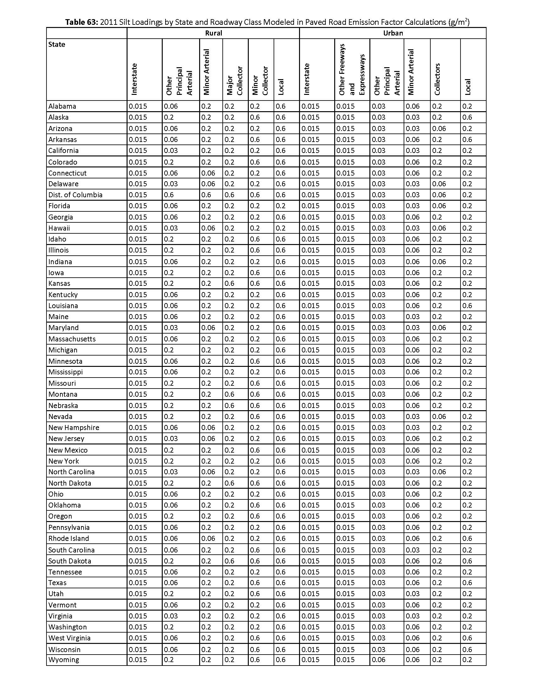
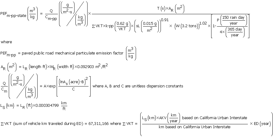
It is assumed that dust is being resuspended from the road surface. The amount of dust on an area of road is called the silt loading factor (SLF). For this calculator, a default value of 0.015 g/m2 was selected from 2011 National Emissions Inventory, version 1 Technical Support Document June 2014 - DRAFT , Table 63, Page 104, concerning paved roads. This value, combined with the California annual vehicle kilometers traveled by length of California interstates, resulted in the most protective PEF. Multiple SLFs were given for specific circumstances. The values range from 0.015 to 0.6 g/m2. The Table is reproduced below. The SLFs for urban collector roadway class are used for both major and minor collector roadway classes found in annual vehicle kilometers traveled by the length of each roadway class. Also, rural interstate roadway class SLFs were used for the "other freeways and expressways" roadway class. The SLF used in the risk equations is the inverse of 0.015 g/m2 converted to units of cm2/kg.
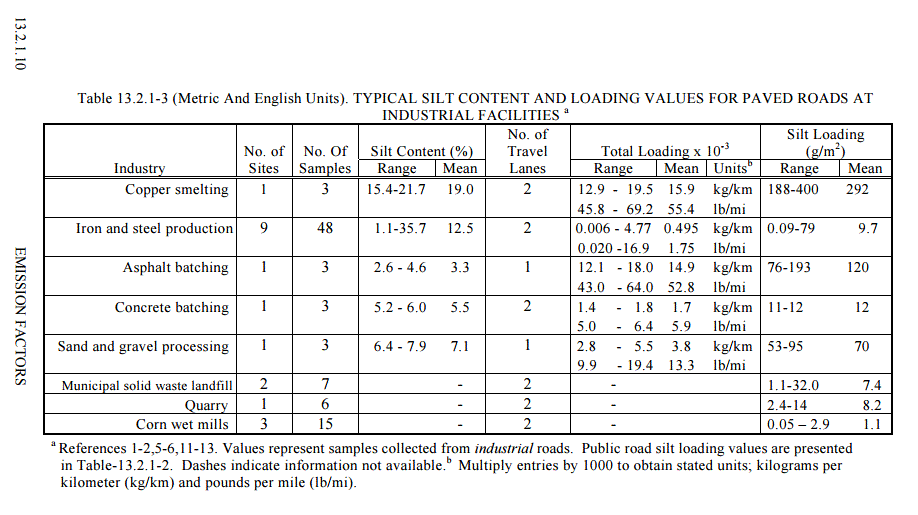
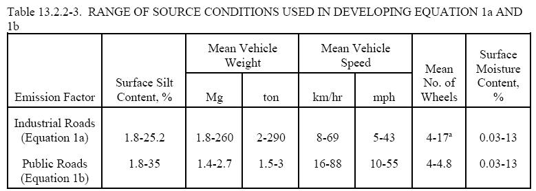
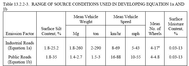
To obtain more accurate SPRG results, the SLF should be measured in the field. Table 13.2.1-3 from AP42 is reproduced below showing the high end typical industrial facility SLF ranges. The values range from 0.09 to 400 g/m2. AP 42 suggests the following:
"Limited access roadways pose severe logistical difficulties in terms of surface sampling, and few silt loading data are available for such roads. Nevertheless, the available data do not suggest great variation in silt loading for limited access roadways from one part of the country to another. For annual conditions, a default value of 0.015 g/m2 is recommended for limited access roadways. Even fewer of the available data correspond to worst-case situations, and elevated loadings are observed to be quickly depleted because of high traffic speeds and high ADT rates. A default value of 0.2 g/m2 is recommended for short periods of time following application of snow/ice controls to limited access roads."
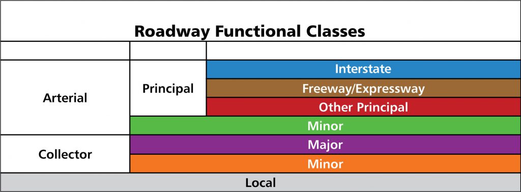
The default state road class and road type, the California urban interstate, yields a mechanical PEF of 1.86 × 10⁶ using a SLF of 0.015 g/m2. This was chosen as the default for this calculator to produce more protective default SPRGs; however, selecting a site-specific state and roadway class will provide a more accurate SLF and VKT. The United States Department of Transportation's Federal Highway Administration maintains an interactive HEPGIS website that supplies a map of the 50 States and Puerto Rico depicting functional roadway classes. The user can use the zoom controls to reach the area of interest. This resource could be consulted to apply site-specific inputs for calculating VKT and SLF for a risk assessment. The color classification schemes are general indicators of functional classes. Roadways are presented for the National Highway system, Eisenhower System, and Federal Highway Administration. A brief description of the classifications are given in here and a detailed description is here. Further state-specific information can be found by consulting the representatives found on this contact list.
The image and table below depict the color schemes.
NHS
ClassificationColor (NHS) Eisenhower Classification Color (Eisenhower) FHWA Functional Classification (Rural) Color (FWHA Rural) FHWA Functional Classification (Urban) Color (FWHA Urban) Interstate Highways Blue Interstate Highways Red Interstate Blue Interstate Blue MAP-21 Principal Arterials Black Principal Arterials Dark Red Other Principal Arterial Red Other PrincipalArterial Red Other NHS Route Red Non-Interstate STRAHNET Brown Major STRAHNET Connector Green NHS Intermodal Connector Purple Intermodal/STRAHNET Connectors Orange Minor Arterials Orange Minor Arterial Green Minor Arterial Green Major Collectors Yellow Major Collector Purple Major Collector Purple Minor Collectors Light Yellow Minor Collector Yellow or Orange Minor Collector Yellow or Orange Local Roads White Local Gray Local Gray Freeways and Expressways Blue Other Freeways and Expressways Brown Other Freeways and Expressways Brown 4.5.11 Area Correction Factor
The RAGS/HHEM Part B model assumes that an individual is exposed to a source geometry that is effectively an infinite slab. The concept of an infinite slab means that the thickness of the contaminated zone and its aerial extent are so large that it behaves as if it were infinite in its physical dimensions. In practice, soil contaminated to a depth greater than about 15 cm and with an aerial extent greater than about 1,000 m2 will create a radiation field comparable to that of an infinite slab (U.S. EPA. 2000a).
Since the assumption of an infinite slab source will result in overly protective PRGs for most residential settings, an adjustment for source area is considered to be an important modification to the RAGS/HHEM Part B model. Thus, an area correction factor, ACF, has been added to the calculation of recommended PRGs. For the 2-D exposure models addressing finite areas, the ACF is made variable by isotope and area for site-specific analysis. In addition, ACFs are now available for all alternate soil analysis source depths (ground plane, 1 cm, 5 cm, 15 cm, and infinite source volume). This calculator allows the user to select from 19 different soil area sizes. If the default mode is selected, the ACF from the most protective area size is selected. If site-specific mode is selected, the user must select the source area. For further information on the derivation of the isotope-specific/area-specific ACF values for 2-D areas see the Center for Radiation Protection Knowledge ACF report and appendix containing +D and +E values. For the calculation of soil area correction factors, a standard soil density of 1.6 g/cm3 has been used. For a description of other EPA default ACF values that predate this guidance, follow the link here.
4.5.12 Street Surfaces Factor Fs-surf
The 3-D direct external exposure equations (building materials and dust) without Fs-surf are single surface equations. The surfaces factor, in the default and site-specific equations, are based on exposure to two vertical surfaces (outside building surfaces on either side of a street) and a horizontal surface (road and sidewalk). This calculator uses the relationship between the dose rate coefficients for exposures in a contaminated outdoor setting and dose rate coefficients for an infinite source to calculate a surfaces factor (Fs-surf). The dose quantity evaluated is the air kerma rate one meter above the sidewalk. The outdoor surfaces are assumed to be contaminated to the same level. Locations in the midpoint of the sidewalk, next to the buildings, and in the middle of the street for building heights of 12.5, 30, 59, 150, and 200 feet were modeled to account for the dose contribution from multiple surfaces. Further, photon energies of each radioisotope were incorporated into the modeling. Please see the attached PDF file for a detailed explanation of the process. Side Walk Dose Rate shows that building height doesn't effect the dose rate significantly after 150 feet. The above link shows a table of the Fs-surf values used in this calculator for each radioisotope. Fs-surf values were calculated for each position-specific and building-height specific combination.
4.5.13 Radionuclide Decay Constant (λ)
The decay constant term (λ), which is based on the half-life of the isotope, is used for some media in nearly all land uses. λ = 0.693/half-life in years (where 0.693=ln(2)). The term (1 - e-λt) takes into account the number of half-lives that will occur within the exposure duration to calculate an appropriate value. For the secular equilibrium SPRG output option, decay is not used. In most cases, site-specific analytical data should be used to establish the actual degree of equilibrium between each parent radionuclide and its decay products in each media sampled. In the absence of empirical data, however, the secular equilibrium SPRGs will provide a protective screening value. Definitions of the input variables are in Table 1.
4.5.14 Gamma Shielding Factors (GSF)
A default gamma shielding factor for indoor exposure to ionizing radiation (GSFi) is established at 0.4 (60% shielding).
A default gamma shielding factor for outdoor exposure to ionizing radiation on surfaces (GSFs) is established at 1 (0% shielding).
4.6 Supporting Equations
The above land use equations require further explanation for particulate emission factors.
4.6.1 Particulate Emission Factors (PEFs)
Two types of particulate emission factors are presented in this calculator: mechanically driven and the traditional wind driven emission factor.
4.6.1.1 Mechanically Driven PEF for Paved Public Roads
These equations allow the user to change site dimensions, distance traveled, mean vehicle weight, road dimensions, particle size multiplier, time, and number of rain days. These equations can be used to simulate emission factors after an incident. The receptor is assumed to be exposed to contaminants in the form of particulate matter with an aerodynamic particle diameter of less than 10 microns (PM10). Fugitive dust emissions are generated by vehicle traffic on paved roads.
The following fugitive dust emission equations represent approximations of actual emissions at a specific site. Sensitive emission model parameters include the soil silt content and mean vehicle weight. Silt is defined as soil particles smaller than 75 micrometers (Fm) in diameter and can be measured as that proportion of soil passing a 200-mesh screen, using the American Society for Testing and Materials (ASTM) Method C-136. Mean vehicle weight is presented in tons. The default value is 3.2 tons, but site-specific values can be used. In general, silt loading and mean vehicle weight are the most sensitive model parameters for which default values have been assigned; however, site-specific values will produce more accurate modeling results. Other emission model parameters have not been assigned default values and are typically defined on a site-specific basis. These parameters include the total distance traveled by vehicles, average vehicle speed, and the area of roadway.
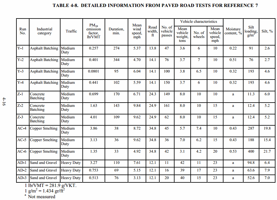
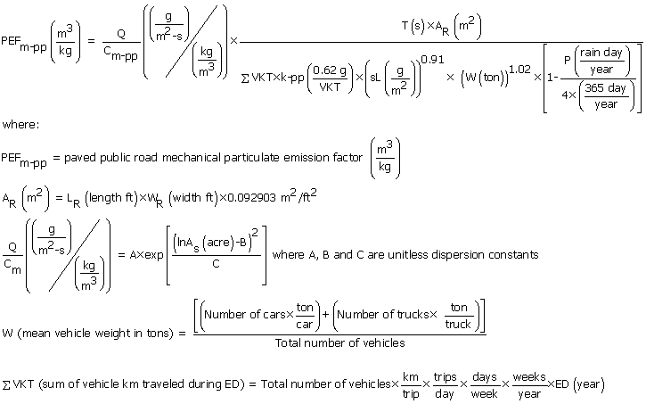
Mean vehicle weight (W) in tons is calculated by determining vehicle weight classes and numbers in that class. An example is presented below for site-specific data. The default mean vehicle weight selected for this calculator is 3.2 tons, based on page 4-285 in Procedures Document for National Emission Inventory, Criteria Air Pollutants 1985-1999. EPA-454/R-01-006. There is wide variation in vehicle weights when considering industrial facilities. AP42 supporting documentation reveals in Table A1-6 that the mean vehicle weight can range up to 42 tons. Site-specific conditions should be considered or measured. The table is reproduced below.
W = [(20 cars × 2 tons/car) + (10 trucks × 20 tons/truck)]/30 vehicles = 8 tons mean vehicle weight.
Sum of vehicle kilometers traveled during the exposure duration, ∑VKT, is estimated based on the size of the area of the contamination, the configuration of the road, and amount of traffic. The default ∑VKT is based on California urban interstate statistics. The value of 2,683,117 kilometers was calculated by multiplying the length of contaminated surface(LS) by the annual vehicle kilometers divided by the total number of kilometers of that road class. This number is then multiplied by the ED. These values resulted in the most protective PEF. The area of the site contamination is assumed to be a square. Therefore, the square root of the area gives the distance traveled in the contaminated area. A half-acre site is 0.002024 km2. The square root is 0.045 km. For the site-specific option of the calculator, the ∑VKT is determined as presented below.
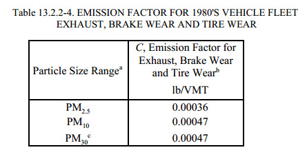
VKT = 30 vehicles × 0.045 km/trip × ps/day × 26 weeks/year × 5 days/week × 25 years (ED) d = 5265 km.The table below is taken from AP42 for Paved Roads and gives values for k.
4.6.1.1.1 State-Specific Equation for Mechanically Driven PEF for Paved Public Roads
Below is the equation used to determine the state-specific and default mechanical PEF for public paved roads. In state-specific mode, the site dimensions, mean vehicle weight, road dimensions, particle size multiplier, time, and number of rain days can be changed. The state, geographic setting, and roadway class must be selected for the equation to operate. The default PEF is based on data for California.
4.6.1.1.2 Site-Specific Equation for Mechanically Driven PEF for Paved Public Roads
Below is the equation used to determine the site-specific mechanical PEF for public paved roads. The site dimensions, road dimensions, particle size multiplier, number of rain days, silt loading factor, mean vehicle weight inputs, time, and ∑VKT inputs can be changed.
4.6.1.2 Mechanically Driven PEF for Unpaved public Roads
This equation allows the user to change emission factor for fleet exhaust, brake and tire wear, silt percentage, silt moisture content, mean vehicle speed, site dimensions, distance traveled, mean vehicle weight, road dimensions, particle size multiplier, time, and number of rain days. The receptor is assumed to be exposed to contaminants in the form of particulate matter with an aerodynamic particle diameter of less than 10 microns (PM10). Fugitive dust emissions are generated by vehicle traffic on unpaved public roads.
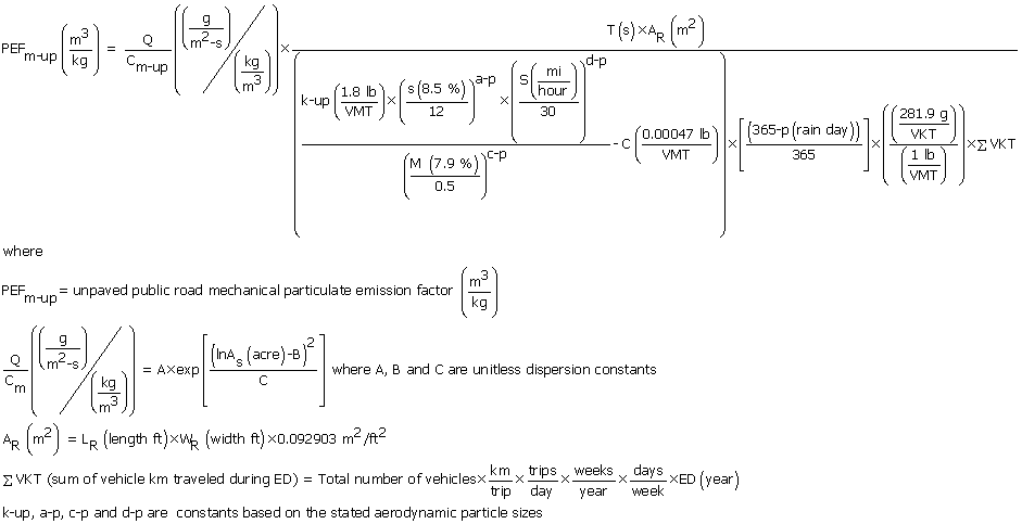
The following fugitive dust emission equation represents approximations of actual emissions at a specific site. Sensitive emission model parameters include the soil silt percentage, silt moisture content, and mean vehicle speed. Silt is defined as soil particles smaller than 75 micrometers (µm) in diameter and can be measured as that proportion of soil passing a 200-mesh screen, using the American Society for Testing and Materials (ASTM) Method C-136. Soil moisture content is defined on a percent gravimetric basis [(g-water/g-soil) × 100] and should be approximated as the mean value for the duration of the construction project. In general, soil silt and moisture content are the most sensitive model parameters for which default values have been assigned;, however, site-specific values will produce more accurate modeling results. Other emission model parameters have not been assigned default values and are typically defined on a site-specific basis. These parameters include the site dimensions and average vehicle speed.
The silt moisture content default is 7.9%; however, moisture can range from 0.03 to 13%, according to AP42 section 13.2.2-3 on unpaved roads. There is wide variation in moisture content when considering industrial facilities. Table 13.2.2-3 is presented below.
Sum of vehicle kilometers traveled during the ED, ∑VKT, is estimated based on the size of the area of the contamination, the configuration of the road, and amount of traffic. There is not a default value for this equation. This equation is only accessible in the site-specific option. The VKT can be determined on a site-specific basis by following the example presented below.
VKT = 30 vehicles × 0.045 km/trip × 1 trips/day × 26 weeks/year × 5 days/week × 30 years (ED) d = 5265 km.
The table below is taken from AP42 for Unpaved Roads and gives values for k.
The table below is taken from AP42 for Unpaved Roads and gives values for C.
The table below is taken from AP42 for Unpaved Roads and gives values for S.
4.6.1.3 Mechanically Driven PEF for Unpaved Industrial Roads
This equation allows the user to change silt percentage, site dimensions, distance traveled, mean vehicle weight, road dimensions, particle size multiplier, time, and number of rain days. The receptor is assumed to be exposed to contaminants in the form of particulate matter with an aerodynamic particle diameter of less than 10 microns (PM10). Fugitive dust emissions are generated by vehicle traffic on unpaved industrial roads.
The following fugitive dust emission equation represents approximations of actual emissions at a specific site. Sensitive emission model parameters include the silt percentage and mean vehicle weight. Silt is defined as soil particles smaller than 75 micrometers (µm) in diameter and can be measured as that proportion of soil passing a 200-mesh screen, using the American Society for Testing and Materials (ASTM) Method C-136. Site-specific values for mean vehicle weight and silt percentage will produce more accurate modeling results. Other emission model parameters have not been assigned default values and are typically defined on a site-specific basis. These parameters include the total distance traveled by vehicles, mean vehicle weight, and the area of the site.
The silt percentage default is 8.5%; however, percentage can range from 1.8 to 25.2%, according to AP42 section on unpaved roads. There is wide variation in silt percentage content when considering industrial facilities. Table 13.2.2-3 is presented below.
W = [(20 cars × 2 tons/car) + (10 trucks × 20 tons/truck)]/30 vehicles = 8 tons mean vehicle weight.
Sum of vehicle kilometers traveled, (VKT), is estimated based on the size of the area of the contamination, the configuration of the road, and amount of traffic. There is not a default value for this equation. This equation is only accessible in the site-specific option. The VKT can be determined on a site-specific basis by following the example presented below.
VKT = 30 vehicles × 0.045 km/trip × 1 trips/day × 26 weeks/year × 5 days/week × 30 years (ED) d = 5265 km.
The table below is taken from AP42 for Unpaved Roads and gives values for k.
4.6.1.4 Wind Driven PEF
This equation allows the user to select geographical regions and input fraction of vegetative cover and wind speed. Inhalation of isotopes adsorbed to respirable particles (PM10) was assessed using default input parameters. This equation relates the contaminant concentration in soil with the concentration of respirable particles in the air due to fugitive dust emissions from contaminated soils. Regional-specific PEFs are derived using default values that correspond to a receptor point concentration of approximately 0.76 ug/m3. The relationship is derived by Cowherd (1985) for a rapid assessment procedure applicable to a typical hazardous waste site, where the surface contamination provides a relatively continuous and constant potential for emission over an extended period of time (e.g., years). This represents an annual average emission rate based on wind erosion that should be compared with chronic health criteria; it is not appropriate for evaluating the potential for more acute exposures. Definitions of the input variables are in Table 1.
The equation below forms the basis for deriving a generic PEF for the inhalation pathway. For more details regarding specific parameters used in the PEF model, refer to Soil Screening Guidance for Radionuclides: Technical Background Document. The use of alternate values on a specific site should be justified and presented in an Administrative Record if considered in CERCLA remedy selection.
Wind-driven
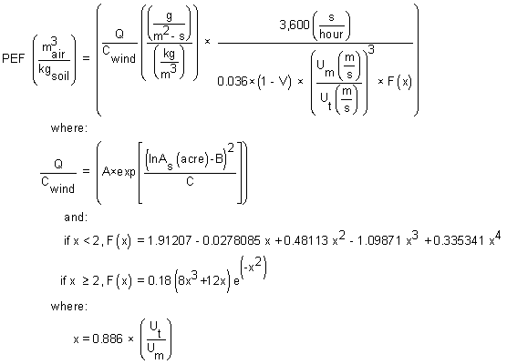
4.6.2 Decay Functions
The following decay functions should be multiplied by their respective CDI equations when applicable:
The following decay functions should be multiplied by their respective PRG equations when applicable:
4.7 Equation Sources and Parameters
This section presents details on some of the equation sources and parameters.
4.7.1 Exposure to Settled Dust on Surfaces Equations
The inadvertent ingestion from materials deposited on surfaces equation was modeled after the equation found in ANL 2001 (Fig 8.3). The ingestion rate term in this equation was modeled after U.S. EPA 2003 (pg. D-4). External exposure from deposited materials equation was modeled after the equation found in ANL 2001 (Fig 8.7).
4.7.2 Direct External Exposure Equations
The direct external exposure from a volume and surface of a large area equation was modeled after ANL 2001 (Fig 8.6). External exposure from deposited materials equation was modeled after the equation found in ANL 2001 (Fig 8.7).
4.7.2.1 External Exposure Equation Derivation
The external exposure pathway dose from exposure to an area or a volume source containing radionuclide n in compartment i,
, is expressed as:
where:
Fin = fraction of time spent indoors;
Fi = fraction of time spent in compartment i;
=average concentration of radionuclide n;
= FGR-12 dose conversion factor for infinite volume source; and
= geometrical factor for finite area, source thickness, shielding, source material, and position of receptor relative to the source for radionuclide n.
The geometrical factor is the ratio of the effective dose equivalent for the actual source to the effective dose equivalent for the standard source. The standard source is a contaminated soil of infinite depth and lateral extent with no cover. The geometrical factor is expressed as the product of the depth-and-cover factor, FCD, an area and material factor, FAM, and the off-set factor, FOFF-SET.So,
= effective dose from actual source/effective dose from standard source.
Then,
= FCD x FAM x FOFF-SET.
4.7.2.1.1 Depth-And-Cover Factor (FCD)
Note: The FCD would traditionally be included in this type of analysis; however, it is not included in the equations for this calculator. This calculator includes depth-specific dose conversion factors for surface (ground plane) and uniformly distributed volume sources at four specific thicknesses (1, 5, and 15 cm and effectively infinite). Inclusion of these dose conversion factors eliminates the need for the FCD.
Dose conversion factors in FGR-12 (Eckerman and Ryman 1993) are given for surface and uniformly distributed volume sources at four specific thicknesses (1, 5, and 15 cm and effectively infinite) with a soil density of 1.6 g/cm3. FGR-12 assumes that sources are infinite in lateral extent. In actual situations, sources can have any depth, shape, cover, and size. A depth and-cover factor function, FCD, was developed with regression analysis to express the attenuation for radionuclides. Three independent radionuclide-specific parameters were determined by using the effective dose equivalent values of FGR-12 at different depths. Kamboj et al. (1998) describes how the depth-and-cover function was derived using the effective dose equivalent values of FGR-12 at different depths. A depth-and-cover factor function was derived from the depth factor function by considering both dose contribution and attenuation from different depths:
where:
A, B = fit parameters (dimensionless);
KA, KB = fit parameters (cm2/g);
tc = shielding thickness (cm) (the sum of all shielding thicknesses between the source and the receptor), the shielding is placed immediately adjacent to the source;
ρc= shielding density (g/cm3)(the thickness-averaged density between the source and receptor);
ts = source thickness (cm);
ρs = source density (g/cm3);
Tc = shielding parameter (m); and
Ts = source depth parameter (m).
The following constraints were put on the four fitting parameters:
1. All the parameters were forced to be positive;
2. A + B = 1; and
3. In the limit source depth, ts → zero, the DCF should match the contaminated surface DCF.
All the four unknown parameters (A, B, KA, and KB) were found for 67 radionuclides available in the RESRAD-BUILD computer code. The fitted values of A, B, KA, and KB for radionuclides were used in the dose calculations.
4.7.2.1.2 Area-And-Material Factor (FAM)
For actual geometries (finite area and different materials), the area and material factor, FAM, was derived by using the point-kernel method. This factor depends not only on the lateral extent of the contamination but also on source thickness, shielding thickness, gamma energies, and source material through its attenuation and buildup factors. All energies from radionuclide decay were considered separately and weighted by its yield, y, energy, E, and an energy dependent coefficient, K, to convert from air-absorbed dose to effective dose equivalent:
where:
(x')2 = r2 + (ta + tc + t)2;
(x)2 = r2 + (1m + t)2;
B and µ are the buildup factor and the attenuation factor, respectively, for the appropriate material (a for air, c for shield material, and s for source material or soil reference). The integration volume V' is the desired geometry of specified material with radius R, shielding thickness tc, and air thickness ta; whereas V is the reference geometry of soil extending infinitely laterally with no shield and the receptor midpoint located 1 m from the surface.
4.7.2.1.3 Off-set Factor ( FOFF-SET)
The off-set factor, FOFF-SET, is the ratio of the dose estimates from a noncircular shaped contaminated material to a reference shape. The concept of the shape factor is used to calculate the off-set factor. The reference shape is a fully contaminated circular area encompassing the given shape, centered about the receptor. This factor is derived by considering the area, material factors of a series of concentric circles, and the corresponding contamination fraction of the annular regions. The off-set factor is obtained by enclosing the irregularly shaped contaminated area in a circle, multiplying the area factor of each annulus by the fraction of the contaminated annulus area, fi, summing the products, and dividing by the area factor of a circular contaminated material that is equivalent in area:
5. Recommended Default Exposure Parameters
Table 1 presents the definitions of the variables and their default values. The SPRG default values and exposure models are consistent with the Dose Compliance Concentrations for Radionuclides in Outdoor Surfaces (SDCC) calculator. Both the SPRG and SDCC default values are largely consistent with default values in the PRG, DCC, BPRG, and SPRG where the same pathways are addressed (e.g., ingestion of dust on hard surfaces). This calculator, and the SDCC, both follow the recommendations in the OSWER Directive concerning use of exposure parameters from the 2011 Exposure Factors Handbook. Any alternative values or assumptions used in remedy evaluation or selection on a CERCLA site should be presented with supporting rationale in Administrative Records.
Table 1. Recommended Default Exposure Parameters
| SPRG Equations | |||
| Symbol | Definition (units) | Default | Reference |
| SPRGres-dust-ing | Resident SPRG for Ingestion Exposure to Settled Dust on Surfaces (pCi/cm2) | Isotope-specific | Determined in this calculator |
| SPRGres-dust-inh | Resident SPRG for Wind Inhalation Exposure to Settled Dust on Surfaces (pCi/cm2) | Isotope-specific | Determined in this calculator |
| SPRGres-dust-inhm | Resident SPRG for Mechanical Inhalation Exposure to Settled Dust on Surfaces (pCi/cm2) | Isotope-specific | Determined in this calculator |
| SPRGres-dust-inh-state | Resident SPRG for State-Specific Wind Inhalation Exposure to Settled Dust on Surfaces (pCi/cm2) | Isotope-specific | Determined in this calculator |
| SPRGres-dust-inhm-state | Resident SPRG for State-Specific Mechanical Inhalation Exposure to Settled Dust on Surfaces (pCi/cm2) | Isotope-specific | Determined in this calculator |
| SPRGres-dust-ext | Resident SPRG for External Exposure to Settled Dust on Surfaces (pCi/cm2) | Isotope-specific | Determined in this calculator |
| SPRGres-dust-tot | Resident SPRG for Total Exposure to Settled Dust on Surfaces (pCi/cm2) | Isotope-specific | Determined in this calculator |
| SPRGres-3D-ext-sv | 3-D Resident SPRG for Direct External Exposure to Contaminated Building Materials using infinite soil volume (pCi/g) | Isotope-specific | Determined in this calculator |
| SPRGres-3D-ext-1cm | 3-D Resident SPRG for Direct External Exposure to Contaminated Building Materials using 1cm soil volume (pCi/g) | Isotope-specific | Determined in this calculator |
| SPRGres-3D-ext-5cm | 3-D Resident SPRG for Direct External Exposure to Contaminated Building Materials using 5 cm soil volume (pCi/g) | Isotope-specific | Determined in this calculator |
| SPRGres-3D-ext-15cm | 3-D Resident SPRG for Direct External Exposure to Contaminated Building Materials using 15 cm soil volume (pCi/g) | Isotope-specific | Determined in this calculator |
| SPRGres-3D-ext-gp | Resident SPRG for Direct External Exposure to Contaminated Dust (pCi/cm2) | Isotope-specific | Determined in this calculator |
| SPRGres-2D-ext-sv | 2-D Resident SPRG for Direct External Exposure to Finite Slabs using infinite soil volume (pCi/g) | Isotope-specific | Determined in this calculator |
| SPRGres-2D-ext-1cm | 2-D Resident SPRG for Direct External Exposure to Finite Slabs using 1cm soil volume (pCi/g) | Isotope-specific | Determined in this calculator |
| SPRGres-2D-ext-5cm | 2-D Resident SPRG for Direct External Exposure to Finite Slabs using 5 cm soil volume (pCi/g) | Isotope-specific | Determined in this calculator |
| SPRGres-2D-ext-15cm | 2-D Resident SPRG for Direct External Exposure to Finite Slabs using 15 cm soil volume (pCi/g) | Isotope-specific | Determined in this calculator |
| SPRGres-2D-ext-gp | Resident SPRG for Direct External Exposure to Contaminated Dust on Finite Slabs (pCi/cm2) | Isotope-specific | Determined in this calculator |
| SPRGow-dust-ing | Outdoor Worker SPRG for Ingestion of Settled Dust on Surfaces (pCi/cm2) | Isotope-specific | Determined in this calculator |
| SPRGow-dust-inh | Outdoor Worker SPRG for Wind Inhalation Exposure to Settled Dust on Surfaces (pCi/cm2) | Isotope-specific | Determined in this calculator |
| SPRGow-dust-inhm | Outdoor Worker SPRG for Mechanical Inhalation Exposure to Settled Dust on Surfaces (pCi/cm2) | Isotope-specific | Determined in this calculator |
| SPRGow-dust-inh-state | Outdoor Worker SPRG for State-Specific Wind Inhalation Exposure to Settled Dust on Surfaces (pCi/cm2) | Isotope-specific | Determined in this calculator |
| SPRGow-dust-inhm-state | Outdoor Worker SPRG for State-Specific Mechanical Inhalation Exposure to Settled Dust on Surfaces (pCi/cm2) | Isotope-specific | Determined in this calculator |
| SPRGow-dust-ext | Outdoor Worker SPRG for Total External Exposure to Settled Dust on Surfaces (pCi/cm2) | Isotope-specific | Determined in this calculator |
| SPRGow-dust-tot | Outdoor Worker SPRG for Total Exposure to Settled Dust on Surfaces (pCi/cm2) | Isotope-specific | Determined in this calculator |
| SPRGow-3D-ext-sv | 3-D Outdoor Worker SPRG for Direct External Exposure to Contaminated Building Materials using infinite soil volume (pCi/g) | Isotope-specific | Determined in this calculator |
| SPRGow-3D-ext-1cm | 3-D Outdoor Worker SPRG for Direct External Exposure to Contaminated Building Materials using 1 cm soil volume (pCi/g) | Isotope-specific | Determined in this calculator |
| SPRGow-3D-ext-5cm | 3-D Outdoor Worker SPRG for Direct External Exposure to Contaminated Building Materials using 5cm soil volume (pCi/g) | Isotope-specific | Determined in this calculator |
| SPRGow-3D-ext-15cm | 3-D Outdoor Worker SPRG for Direct External Exposure to Contaminated Building Materials using 15cm soil volume (pCi/g) | Isotope-specific | Determined in this calculator |
| SPRGow-3D-ext-gp | 3-D Outdoor Worker SPRG for Direct External Exposure to Contaminated Dust (pCi/cm2) | Isotope-specific | Determined in this calculator |
| SPRGow-2D-ext-sv | 2-D Outdoor Worker SPRG for Direct External Exposure to Finite Slabs using infinite soil volume (pCi/g) | Isotope-specific | Determined in this calculator |
| SPRGow-2D-ext-1cm | 2-D Outdoor Worker SPRG for Direct External Exposure to Finite Slabs using 1 cm soil volume (pCi/g) | Isotope-specific | Determined in this calculator |
| SPRGow-2D-ext-5cm | 2-D Outdoor Worker SPRG for Direct External Exposure to Finite Slabs using 5cm soil volume (pCi/g) | Isotope-specific | Determined in this calculator |
| SPRGow-2D-ext-15cm | 2-D Outdoor Worker SPRG for Direct External Exposure to Finite Slabs using 15cm soil volume (pCi/g) | Isotope-specific | Determined in this calculator |
| SPRGow-2D-ext-gp | 2-D Outdoor Worker SPRG for Direct External Exposure to Contaminated Dust on Finite Slabs (pCi/cm2) | Isotope-specific | Determined in this calculator |
| SPRGiw-dust-ing | Indoor Worker SPRG for Ingestion Exposure to Settled Dust on Surfaces (pCi/cm2) | Isotope-specific | Determined in this calculator |
| SPRGiw-dust-inh | Indoor Worker SPRG for Wind Inhalation Exposure to Settled Dust on Surfaces (pCi/cm2) | Isotope-specific | Determined in this calculator |
| SPRGiw-dust-inhm | Indoor Worker SPRG for Mechanical Inhalation Exposure to Settled Dust on Surfaces (pCi/cm2) | Isotope-specific | Determined in this calculator |
| SPRGiw-dust-inh-state | Indoor Worker SPRG for State-Specific Wind Inhalation Exposure to Settled Dust on Surfaces (pCi/cm2) | Isotope-specific | Determined in this calculator |
| SPRGiw-dust-inhm-state | Indoor Worker SPRG for State-Specific Mechanical Inhalation Exposure to Settled Dust on Surfaces (pCi/cm2) | Isotope-specific | Determined in this calculator |
| SPRGiw-dust-ext | Indoor Worker SPRG for External Exposure to Settled Dust on Surfaces (pCi/cm2) | Isotope-specific | Determined in this calculator |
| SPRGiw-dust-tot | Indoor Worker SPRG for Total Exposure to Settled Dust on Surfaces (pCi/cm2) | Isotope-specific | Determined in this calculator |
| SPRGiw-3D-ext-dust-sv | 3-D Indoor Worker SPRG for Direct External Exposure to Contaminated Building Materials using infinite soil volume (pCi/g) | Isotope-specific | Determined in this calculator |
| SPRGiw-3D-ext-dust-1cm | 3-D Indoor Worker SPRG for Direct External Exposure to Contaminated Building Materials using 1 cm soil volume (pCi/g) | Isotope-specific | Determined in this calculator |
| SPRGiw-3D-ext-dust-5cm | 3-D Indoor Worker SPRG for Direct External Exposure to Contaminated Building Materials using 5 cm soil volume (pCi/g) | Isotope-specific | Determined in this calculator |
| SPRGiw-3D-ext-dust-15cm | 3-D Indoor Worker SPRG for Direct External Exposure to Contaminated Building Materials using 15 cm soil volume (pCi/g) | Isotope-specific | Determined in this calculator |
| SPRGiw-3D-ext-dust-gp | 3-D Indoor Worker SPRG for Direct External Exposure to Contaminated Dust (pCi/cm2) | Isotope-specific | Determined in this calculator |
| SPRGiw-2D-ext-dust-sv | 2-D Indoor Worker SPRG for Direct External Exposure to Finite Slabs using infinite soil volume (pCi/g) | Isotope-specific | Determined in this calculator |
| SPRGiw-2D-ext-dust-1cm | 2-D Indoor Worker SPRG for Direct External Exposure to Finite Slabs using 1 cm soil volume (pCi/g) | Isotope-specific | Determined in this calculator |
| SPRGiw-3D-ext-dust-5cm | 2-D Indoor Worker SPRG for Direct External Exposure to Finite Slabs using 5 cm soil volume (pCi/g) | Isotope-specific | Determined in this calculator |
| SPRGiw-2D-ext-dust-15cm | 2-D Indoor Worker SPRG for Direct External Exposure to Finite Slabs using 15 cm soil volume (pCi/g) | Isotope-specific | Determined in this calculator |
| SPRGiw-2D-ext-dust-gp | 2-D Indoor Worker SPRG for Direct External Exposure to Contaminated Dust on Finite Slabs (pCi/cm2) | Isotope-specific | Determined in this calculator |
| SPRGw-dust-ing | Composite Worker SPRG for Ingestion Exposure to Settled Dust on Surfaces (pCi/cm2) | Isotope-specific | Determined in this calculator |
| SPRGw-dust-inh | Composite Worker SPRG for Wind Inhalation Exposure to Settled Dust on Surfaces (pCi/cm2) | Isotope-specific | Determined in this calculator |
| SPRGw-dust-inhm | Composite Worker SPRG for Mechanical Inhalation Exposure to Settled Dust on Surfaces (pCi/cm2) | Isotope-specific | Determined in this calculator |
| SPRGw-dust-inh-state | Composite Worker SPRG for State-Specific Wind Inhalation Exposure to Settled Dust on Surfaces (pCi/cm2) | Isotope-specific | Determined in this calculator |
| SPRGw-dust-inhm-state | Composite Worker SPRG for State-Specific Mechanical Inhalation Exposure to Settled Dust on Surfaces (pCi/cm2) | Isotope-specific | Determined in this calculator |
| SPRGw-dust-ext | Composite Worker SPRG for External Exposure to Settled Dust on Surfaces (pCi/cm2) | Isotope-specific | Determined in this calculator |
| SPRGw-dust-tot | Composite Worker SPRG for Total Exposure to Settled Dust on Surfaces (pCi/cm2) | Isotope-specific | Determined in this calculator |
| SPRGw-3D-ext-sv | 3-D Composite Worker SPRG for Direct External Exposure to Contaminated Building Materials using infinite soil volume (pCi/g) | Isotope-specific | Determined in this calculator |
| SPRGw-3D-ext-1cm | 3-D Composite Worker SPRG for Direct External Exposure to Contaminated Building Materials using 1 cm soil volume (pCi/g) | Isotope-specific | Determined in this calculator |
| SPRGw-3D-ext-5cm | 3-D Composite Worker SPRG for Direct External Exposure to Contaminated Building Materials using 5 cm soil volume (pCi/g) | Isotope-specific | Determined in this calculator |
| SPRGw-3D-ext-15cm | 3-D Composite Worker SPRG for Direct External Exposure to Contaminated Building Materials using 15 cm soil volume (pCi/g) | Isotope-specific | Determined in this calculator |
| SPRGw-3D-ext-gp | 3-D Composite Worker SPRG for Direct External Exposure to Contaminated Dust (pCi/cm2) | Isotope-specific | Determined in this calculator |
| SPRGw-2D-ext-sv | 2-D Composite Worker SPRG for Direct External Exposure to Finite Slabs using infinite soil volume (pCi/g) | Isotope-specific | Determined in this calculator |
| SPRGw-2D-ext-1cm | 2-D Composite Worker SPRG for Direct External Exposure to Finite Slabs using 1 cm soil volume (pCi/g) | Isotope-specific | Determined in this calculator |
| SPRGw-3D-ext-5cm | 2-D Composite Worker SPRG for Direct External Exposure to Finite Slabs using 5 cm soil volume (pCi/g) | Isotope-specific | Determined in this calculator |
| SPRGw-2D-ext-15cm | 2-D Composite Worker SPRG for Direct External Exposure to Finite Slabs using 15 cm soil volume (pCi/g) | Isotope-specific | Determined in this calculator |
| SPRGw-2D-ext-gp | 2-D Composite Worker SPRG for Direct External Exposure to Contaminated Dust on Finite Slabs (pCi/cm2) | Isotope-specific | Determined in this calculator |
| CDI Equations | |||
| Symbol | Definition (units) | Default | Reference |
| CDIres-dust-ing | Resident CDI for Ingestion Exposure to Settled Dust on Surfaces (pCi) | Isotope-specific | Determined in this calculator |
| CDIres-dust-inh | Resident CDI for Wind Inhalation Exposure to Settled Dust on Surfaces (pCi) | Isotope-specific | Determined in this calculator |
| CDIres-dust-inhm | Resident CDI for Mechanical Inhalation Exposure to Settled Dust on Surfaces (pCi) | Isotope-specific | Determined in this calculator |
| CDIres-dust-inh-state | Resident CDI for State-Specific Wind Inhalation Exposure to Settled Dust on Surfaces (pCi) | Isotope-specific | Determined in this calculator |
| CDIres-dust-inhm-state | Resident CDI for State-Specific Mechanical Inhalation Exposure to Settled Dust on Surfaces (pCi) | Isotope-specific | Determined in this calculator |
| CDIres-dust-ext | Resident CDI for External Exposure to Settled Dust on Surfaces (pCi-year/cm2) | Isotope-specific | Determined in this calculator |
| CDIres-3D-ext-sv | 3-D Resident CDI for Direct External Exposure to Contaminated Building Materials using infinite soil volume (pCi-year/g) | Isotope-specific | Determined in this calculator |
| CDIres-3D-ext-1cm | 3-D Resident CDI for Direct External Exposure to Contaminated Building Materials using 1cm soil volume (pCi-year/g) | Isotope-specific | Determined in this calculator |
| CDIres-3D-ext-5cm | 3-D Resident CDI for Direct External Exposure to Contaminated Building Materials using 5 cm soil volume (pCi-year/g) | Isotope-specific | Determined in this calculator |
| CDIres-3D-ext-15cm | 3-D Resident CDI for Direct External Exposure to Contaminated Building Materials using 15 cm soil volume (pCi-year/g) | Isotope-specific | Determined in this calculator |
| CDIres-3D-ext-gp | Resident CDI for Direct External Exposure to Contaminated Dust (pCi-year/cm2) | Isotope-specific | Determined in this calculator |
| CDIres-2D-ext-sv | 2-D Resident CDI for Direct External Exposure to Finite Slabs using infinite soil volume (pCi-year/g) | Isotope-specific | Determined in this calculator |
| CDIres-2D-ext-1cm | 2-D Resident CDI for Direct External Exposure to Finite Slabs using 1cm soil volume (pCi-year/g) | Isotope-specific | Determined in this calculator |
| CDIres-2D-ext-5cm | 2-D Resident CDI for Direct External Exposure to Finite Slabs using 5 cm soil volume (pCi-year/g) | Isotope-specific | Determined in this calculator |
| CDIres-2D-ext-15cm | 2-D Resident CDI for Direct External Exposure to Finite Slabs using 15 cm soil volume (pCi-year/g) | Isotope-specific | Determined in this calculator |
| CDIres-2D-ext-gp | Resident CDI for Direct External Exposure to Contaminated Dust on Finite Slabs (pCi-year/cm2) | Isotope-specific | Determined in this calculator |
| CDIow-dust-ing | Outdoor Worker CDI for Ingestion of Settled Dust on Surfaces (pCi) | Isotope-specific | Determined in this calculator |
| CDIow-dust-inh | Outdoor Worker CDI for Wind Inhalation Exposure to Settled Dust on Surfaces (pCi) | Isotope-specific | Determined in this calculator |
| CDIow-dust-inhm | Outdoor Worker CDI for Mechanical Inhalation Exposure to Settled Dust on Surfaces (pCi) | Isotope-specific | Determined in this calculator |
| CDIow-dust-inh-state | Outdoor Worker CDI for State-Specific Wind Inhalation Exposure to Settled Dust on Surfaces (pCi) | Isotope-specific | Determined in this calculator |
| CDIow-dust-inhm-state | Outdoor Worker CDI for State-Specific Mechanical Inhalation Exposure to Settled Dust on Surfaces (pCi) | Isotope-specific | Determined in this calculator |
| CDIow-dust-ext | Outdoor Worker CDI for Total External Exposure to Settled Dust on Surfaces (pCi-year/cm2) | Isotope-specific | Determined in this calculator |
| CDIow-3D-ext-sv | 3-D Outdoor Worker CDI for Direct External Exposure to Contaminated Building Materials using infinite soil volume (pCi-year/g) | Isotope-specific | Determined in this calculator |
| CDIow-3D-ext-1cm | 3-D Outdoor Worker CDI for Direct External Exposure to Contaminated Building Materials using 1 cm soil volume (pCi-year/g) | Isotope-specific | Determined in this calculator |
| CDIow-3D-ext-5cm | 3-D Outdoor Worker CDI for Direct External Exposure to Contaminated Building Materials using 5cm soil volume (pCi-year/g) | Isotope-specific | Determined in this calculator |
| CDIow-3D-ext-15cm | 3-D Outdoor Worker CDI for Direct External Exposure to Contaminated Building Materials using 15cm soil volume (pCi-year/g) | Isotope-specific | Determined in this calculator |
| CDIow-3D-ext-gp | 3-D Outdoor Worker CDI for Direct External Exposure to Contaminated Dust (pCi-year/cm2) | Isotope-specific | Determined in this calculator |
| CDIow-2D-ext-sv | 2-D Outdoor Worker CDI for Direct External Exposure to Finite Slabs using infinite soil volume (pCi-year/g) | Isotope-specific | Determined in this calculator |
| CDIow-2D-ext-1cm | 2-D Outdoor Worker CDI for Direct External Exposure to Finite Slabs using 1 cm soil volume (pCi-year/g) | Isotope-specific | Determined in this calculator |
| CDIow-2D-ext-5cm | 2-D Outdoor Worker CDI for Direct External Exposure to Finite Slabs using 5cm soil volume (pCi-year/g) | Isotope-specific | Determined in this calculator |
| CDIow-2D-ext-15cm | 2-D Outdoor Worker CDI for Direct External Exposure to Finite Slabs using 15cm soil volume (pCi-year/g) | Isotope-specific | Determined in this calculator |
| CDIow-2D-ext-gp | 2-D Outdoor Worker CDI for Direct External Exposure to Contaminated Dust on Finite Slabs (pCi-year/cm2) | Isotope-specific | Determined in this calculator |
| CDIiw-dust-ing | Indoor Worker CDI for Ingestion Exposure to Settled Dust on Surfaces (pCi) | Isotope-specific | Determined in this calculator |
| CDIiw-dust-inh | Indoor Worker CDI for Wind Inhalation Exposure to Settled Dust on Surfaces (pCi) | Isotope-specific | Determined in this calculator |
| CDIiw-dust-inhm | Indoor Worker CDI for Mechanical Inhalation Exposure to Settled Dust on Surfaces (pCi) | Isotope-specific | Determined in this calculator |
| CDIiw-dust-inh-state | Indoor Worker CDI for State-Specific Wind Inhalation Exposure to Settled Dust on Surfaces (pCi) | Isotope-specific | Determined in this calculator |
| CDIiw-dust-inhm-state | Indoor Worker CDI for State-Specific Mechanical Inhalation Exposure to Settled Dust on Surfaces (pCi) | Isotope-specific | Determined in this calculator |
| CDIiw-dust-ext | Indoor Worker CDI for External Exposure to Settled Dust on Surfaces (pCi-year/cm2) | Isotope-specific | Determined in this calculator |
| CDIiw-3D-ext-dust-sv | 3-D Indoor Worker CDI for Direct External Exposure to Contaminated Building Materials using infinite soil volume (pCi-year/g) | Isotope-specific | Determined in this calculator |
| CDIiw-3D-ext-dust-1cm | 3-D Indoor Worker CDI for Direct External Exposure to Contaminated Building Materials using 1 cm soil volume (pCi-year/g) | Isotope-specific | Determined in this calculator |
| CDIiw-3D-ext-dust-5cm | 3-D Indoor Worker CDI for Direct External Exposure to Contaminated Building Materials using 5 cm soil volume (pCi-year/g) | Isotope-specific | Determined in this calculator |
| CDIiw-3D-ext-dust-15cm | 3-D Indoor Worker CDI for Direct External Exposure to Contaminated Building Materials using 15 cm soil volume (pCi-year/g) | Isotope-specific | Determined in this calculator |
| CDIiw-3D-ext-dust-gp | 3-D Indoor Worker CDI for Direct External Exposure to Contaminated Dust (pCi-year/cm2) | Isotope-specific | Determined in this calculator |
| CDIiw-2D-ext-dust-sv | 2-D Indoor Worker CDI for Direct External Exposure to Finite Slabs using infinite soil volume (pCi-year/g) | Isotope-specific | Determined in this calculator |
| CDIiw-2D-ext-dust-1cm | 2-D Indoor Worker CDI for Direct External Exposure to Finite Slabs using 1 cm soil volume (pCi-year/g) | Isotope-specific | Determined in this calculator |
| CDIiw-3D-ext-dust-5cm | 2-D Indoor Worker CDI for Direct External Exposure to Finite Slabs using 5 cm soil volume (pCi-year/g) | Isotope-specific | Determined in this calculator |
| CDIiw-2D-ext-dust-15cm | 2-D Indoor Worker CDI for Direct External Exposure to Finite Slabs using 15 cm soil volume (pCi-year/g) | Isotope-specific | Determined in this calculator |
| CDIiw-2D-ext-dust-gp | 2-D Indoor Worker CDI for Direct External Exposure to Contaminated Dust on Finite Slabs (pCi-year/cm2) | Isotope-specific | Determined in this calculator |
| CDIw-dust-ing | Composite Worker CDI for Ingestion Exposure to Settled Dust on Surfaces (pCi) | Isotope-specific | Determined in this calculator |
| CDIw-dust-inh | Composite Worker CDI for Wind Inhalation Exposure to Settled Dust on Surfaces (pCi) | Isotope-specific | Determined in this calculator |
| CDIw-dust-inhm | Composite Worker CDI for Mechanical Inhalation Exposure to Settled Dust on Surfaces (pCi) | Isotope-specific | Determined in this calculator |
| CDIw-dust-inh-state | Composite Worker CDI for State-Specific Wind Inhalation Exposure to Settled Dust on Surfaces (pCi) | Isotope-specific | Determined in this calculator |
| CDIw-dust-inhm-state | Composite Worker CDI for State-Specific Mechanical Inhalation Exposure to Settled Dust on Surfaces (pCi) | Isotope-specific | Determined in this calculator |
| CDIw-dust-ext | Composite Worker CDI for External Exposure to Settled Dust on Surfaces (pCi) | Isotope-specific | Determined in this calculator |
| CDIw-3D-ext-sv | 3-D Composite Worker CDI for Direct External Exposure to Contaminated Building Materials using infinite soil volume (pCi-year/g) | Isotope-specific | Determined in this calculator |
| CDIw-3D-ext-1cm | 3-D Composite Worker CDI for Direct External Exposure to Contaminated Building Materials using 1 cm soil volume (pCi-year/g) | Isotope-specific | Determined in this calculator |
| CDIw-3D-ext-5cm | 3-D Composite Worker CDI for Direct External Exposure to Contaminated Building Materials using 5 cm soil volume (pCi-year/g) | Isotope-specific | Determined in this calculator |
| CDIw-3D-ext-15cm | 3-D Composite Worker CDI for Direct External Exposure to Contaminated Building Materials using 15 cm soil volume (pCi-year/g) | Isotope-specific | Determined in this calculator |
| CDIw-3D-ext-gp | 3-D Composite Worker CDI for Direct External Exposure to Contaminated Dust (pCi-year/cm2) | Isotope-specific | Determined in this calculator |
| CDIw-2D-ext-sv | 2-D Composite Worker CDI for Direct External Exposure to Finite Slabs using infinite soil volume (pCi-year/g) | Isotope-specific | Determined in this calculator |
| CDIw-2D-ext-1cm | 2-D Composite Worker CDI for Direct External Exposure to Finite Slabs using 1 cm soil volume (pCi-year/g) | Isotope-specific | Determined in this calculator |
| CDIw-3D-ext-5cm | 2-D Composite Worker CDI for Direct External Exposure to Finite Slabs using 5 cm soil volume (pCi-year/g) | Isotope-specific | Determined in this calculator |
| CDIw-2D-ext-15cm | 2-D Composite Worker CDI for Direct External Exposure to Finite Slabs using 15 cm soil volume (pCi-year/g) | Isotope-specific | Determined in this calculator |
| CDIw-2D-ext-gp | 2-D Composite Worker CDI for Direct External Exposure to Contaminated Dust on Finite Slabs (pCi-year/cm2) | Isotope-specific | Determined in this calculator |
| Slope Factors | |||
| Symbol | Definition (units) | Default | Reference |
| SFi | Inhalation Slope Factor - air (risk/pCi) | Isotope-specific | ORNL 2014c |
| SFo | Dust Ingestion Slope Factor - population (risk/pCi) | Isotope-specific | ORNL 2014c |
| SFoa | Dust Ingestion Slope Factor - adult only (risk/pCi) | Isotope-specific | ORNL 2014c |
| SFext-gp | External Exposure Slope Factor - dust (risk/year per pCi/cm2) | Isotope-specific | ORNL 2014c |
| SFext-sv | External Exposure Slope Factor - direct (risk/year per pCi/g) | Isotope-specific | ORNL 2014c |
| SFext-1cm | External Exposure Slope Factor - direct (risk/year per pCi/g) | Isotope-specific | ORNL 2014c |
| SFext-5cm | External Exposure Slope Factor - direct (risk/year per pCi/g) | Isotope-specific | ORNL 2014c |
| SFext-15cm | External Exposure Slope Factor - direct (risk/year per pCi/g) | Isotope-specific | ORNL 2014c |
| Dose and Decay Constant Variables | |||
| Symbol | Definition (units) | Default | Reference |
| TR | Target Risk | 1E-06 | U.S. EPA 1990 (pg. 8718-8719) |
| tres | Time - resident (year) | 26 | U.S. EPA 2011a, Table 16-108; 90th percentile or current residence time. |
| tow | Time - outdoor worker (year) | 25 | U.S. EPA 1991 (pg. 15) |
| tiw | Time - indoor worker (year) | 25 | U.S. EPA 1991 (pg. 15) |
| tw | Time - composite worker (year) | 25 | U.S. EPA 1991 (pg. 15) |
| λ | decay constant = 0.693/half-life (year-1) where 0.693 = ln(2) |
Isotope-specific | Developed for EPA's "Preliminary Remediation Goals for Radionuclide Contaminants at Superfund Sites" (NRCP 1996) |
| k | Dissipation Rate Constant (year-1) | 0.38 | U.S. EPA 2003 (pg. D-8) |
| Miscellaneous Variables | |||
| Symbol | Definition (units) | Default | Reference |
| ACFext-sv | Area Correction Factor - soil volume (unitless) | Isotope-specific | ORNL 2014a |
| ACFext-1cm | Area Correction Factor - 1cm (unitless) | Isotope-specific | ORNL 2014a |
| ACFext-5cm | Area Correction Factor - 5cm (unitless) | Isotope-specific | ORNL 2014a |
| ACFext-15cm | Area Correction Factor - 15cm (unitless) | Isotope-specific | ORNL 2014a |
| ACFext-gp | Area Correction Factor - ground plane (unitless) | Isotope-specific | ORNL 2014a |
| SLF | Silt Loading Factor (cm2/kg) | 6.67E+08 | Converted from 0.015 gram/m2. A default number for California highway from Table 2, pg A-67 U.S. EPA 2005. |
| GSFs | Gamma Shielding Factor - Outdoor Surfaces (unitless) | 1 (assumes no shielding) | Other GSFs are presented in these reports. U.S. EPA 2000a. (pg. 2-22). U.S. EPA 2000b. (pg. 2-18) |
| GSFi | Gamma Shielding Factor - Indoor (unitless) | 0.4 (assumes 60% shielding) | Other GSFs are presented in these reports. U.S. EPA 2000a. (pg. 2-22). U.S. EPA 2000b. (pg. 2-18) |
| FAM | Area and Material Factor (unitless) | 1.0 | ANL 2001 (Fig 8.6) |
| FOFF-SET | Off-set Factor (unitless) | 1.0 | ANL 2001 (Fig 8.6) |
| Fs-surf | Street Surfaces Factor (unitless) | isotope-specific | Eckerman 2007 |
| Cdust | Concentration in dust (pCi/cm2) | isotope-specific | site-specific |
| Csoil | Concentration in soil (pCi/g) or (pCi/cm2) | isotope-specific | site-specific |
| Inhalation and Ingestion Rates | |||
| Symbol | Definition (units) | Default | Reference |
| IFDres-adj | Age-Adjusted Dust Ingestion Fraction - Resident (cm2) | 1,022,000 | Calculated Value based on U.S. EPA 2003 (pg. D-4) |
| IFDow | Outdoor Worker Dust Ingestion Factor (cm2/day) | 196 | Calculated Value based on U.S. EPA 2003 (pg. D-4) |
| IFDiw | Indoor Worker Dust Ingestion Factor (cm2/day) | 294 | Calculated Value based on U.S. EPA 2003 (pg. D-4) |
| IFDw | Composite Worker Dust Ingestion Factor (cm2/day) | 196 | Calculated Value based on U.S. EPA 2003 (pg. D-4) |
| IFAres-adj | Age-adjusted Dust Inhalation Fraction (m3) | 161,000 | Calculated Value based on U.S. EPA 1991 (pg. 15) |
| IRAres-a | Adult Dust Inhalation Rate (m3/day; based on IRIS default) | 20 | U.S. EPA 1991 (pg. 15) |
| IRAres-c | Child Dust Inhalation Rate (m3/day; based on IRIS default) | 10 | U.S. EPA 1991 (pg. 15) |
| IRAow | Outdoor Worker Inhalation Rate (m3/hour) | 2.5 | U.S. EPA 1997 (pg. 5-25) |
| IRAiw | Indoor Worker Inhalation Rate (m3/hour) | 2.5 | U.S. EPA 1997 (pg. 5-25) |
| IRAw | Composite Worker Inhalation Rate (m3/hour) | 2.5 | U.S. EPA 1997 (pg. 5-25) |
| Exposure Variables | |||
| Symbol | Definition (units) | Default | Reference |
| FTSSh | Fraction Transferred Surface to Skin - Hard Surface (unitless) | 0.5 | U.S. EPA 2003 (pg. D-3) |
| SAres-a | Surface Area of Fingers - Adult (cm2) | 49 | U.S. EPA 2011 Table 7.2. 5% of the average of adult male and female. |
| SAres-c | Surface Area of Fingers - Child (cm2) | 16 | U.S. EPA 2011 Table 7.2. 5% of the average of adult male and female. |
| SAow | Surface Area of Fingers - Outdoor Worker (cm2) | 49 | U.S. EPA 2011 Table 7.2. 5% of the average of adult male and female. |
| SAiw | Surface Area of Fingers - Indoor Worker (cm2) | 49 | U.S. EPA 2011 Table 7.2. 5% of the average of adult male and female. |
| SAw | Surface Area of Fingers - Composite Worker (cm2) | 49 | U.S. EPA 2011 Table 7.2. 5% of the average of adult male and female. |
| FQres-a | Frequency of Hand to Mouth - Adult (event/hour) | 2 (outdoor) 3 (indoor) |
U.S. EPA 2011 Table 4.1 and EPA 2003. Time weighted average of all age groups from 6 to 26 years. |
| FQres-c | Frequency of Hand to Mouth - Child(event/hour) | 10 (outdoor) 17 (indoor) |
U.S. EPA 2011 Table 4.1 and EPA 2003. Time weighted average of all age groups from birth to 6 years. |
| FQow | Frequency of Hand to Mouth - Outdoor Worker (event/hour) | 2 | U.S. EPA 2011 Table 4.1 and EPA 2003. Time weighted average of all age groups from 6 to 26 years. |
| FQiw | Frequency of Hand to Mouth - Indoor Worker (event/hour) | 3 | U.S. EPA 2011 Table 4.1 and EPA 2003. Time weighted average of all age groups from 6 to 26 years. |
| FQw | Frequency of Hand to Mouth - Composite Worker (event/hour) | 3 | U.S. EPA 2011 Table 4.1 and EPA 2003. Time weighted average of all age groups from 6 to 26 years. |
| SE | Saliva Extraction Factor (unitless) | 0.5 | U.S. EPA 2003 (pg. D-5) |
| ETres-a,h | Exposure Time - Adult Hard Surface (hour/day) | 4 | U.S. EPA 2003 (pg. D-4) |
| ETres-c,h | Exposure Time - Child Hard Surface (hour/day) | 4 | U.S. EPA 2003 (pg. D-4) |
| ETow,h | Exposure Time - Outdoor Worker Hard Surface (hour/day) | 8 | U.S. EPA 2003 (pg. D-4) |
| ETiw,h | Exposure Time - Indoor Worker Hard Surface (hour/day) | 8 | U.S. EPA 2003 (pg. D-4) |
| ETw,h | Exposure Time - Composite Worker Hard Surface (hour/day) | 8 | U.S. EPA 2003 (pg. D-4) |
| ETres-o | Exposure Time Outdoor - Resident (hour/day) | 1.752 | U.S. EPA 1997 (Table 15-132) |
| ETres-i | Exposure Time Indoor - Resident (hour/day) | 16.4 | U.S. EPA 1997 (Table 15-131) |
| ETow | Exposure Time - Outdoor Worker (hour/day) | 8 | U.S. EPA 2003 (pg. D-4) |
| ETiw | Exposure Time - Indoor Worker (hour/day) | 8 | U.S. EPA 2003 (pg. D-4) |
| ETw | Exposure Time - Composite Worker (hour/day) | 8 | U.S. EPA 2003 (pg. D-4) |
| EFiw | Exposure Frequency - indoor worker (day/year) | 250 | U.S. EPA 1991 (pg. 15) |
| EFow | Exposure Frequency - outdoor worker (day/year) | 225 | U.S. EPA 1991 (pg. 15) |
| EFw | Exposure Frequency - composite worker (day/year) | 225 | U.S. EPA 1991 (pg. 15) |
| EFres | Exposure Frequency - resident (day/year) | 350 | U.S. EPA 1991 (pg. 15) |
| EDres | Exposure Duration - resident (year) | 26 | U.S. EPA 2011a, Table 16-108; 90th percentile or current residence time. |
| EDres-a | Exposure Duration - adult resident (year) | 20 | EDres(26 years)-EDres-c(6 years) |
| EDres-c | Exposure Duration - child resident (year) | 6 | U.S. EPA 1991 (pg. 15) |
| EDow | Exposure Duration - outdoor worker (year) | 25 | U.S. EPA 1991 (pg. 15) |
| EDiw | Exposure Duration - indoor worker (year) | 25 | U.S. EPA 1991 (pg. 15) |
| EDw | Exposure Duration - composite worker (year) | 25 | U.S. EPA 1991 (pg. 15) |
| Particulate Emission Factor Variables | |||
| Symbol | Definition (units) | Default | Reference |
| PEFw | Wind Particulate Emission Factor - Minneapolis (m3/kg) | 1.36×10⁹ Minneapolis-specific | U.S. EPA 1996a (pg. 23), U.S. EPA 1996b (pg. 31) |
| Q/Cw | Inverse of the Mean Concentration at the Center of a 0.5-Acre-Square Source - wind(g/m2-s per kg/m3) |
93.77 Minneapolis-specific | U.S. EPA 1996a (pg. 23), U.S. EPA 1996b (pg. 31) |
| V | (fraction of vegetative cover) unitless | 0.5 | U.S. EPA 1999b, U.S. EPA 1996a (pg. 23), U.S. EPA 1996b (pg. 31) |
| Um | (mean annual wind speed) m/s | 4.69 | U.S. EPA 1996, Appendix D Table 2 |
| Ut | (equivalent threshold value of wind speed at 7m) m/s | 11.32 | U.S. EPA 1996, Appendix D Table 2 |
| F(x) | function dependent on 0.886 × (Ut/Um) unitless | 0.194 | U.S. EPA 1996, Appendix D Table 2 |
| A | Dispersion constant - wind (unitless) region-specific Dispersion constant - mechanical (unitless) |
16.2302 - wind default 12.9351 - mechanical |
wind - U.S. EPA 2002 (pg. D-6) mechanical - U.S. EPA 2002 (Eq. E-19) |
| As | Areal extent of the site or contamination (acres) | 0.5 (range 0.5 to 500 ) | U.S. EPA 2002 (pg. D-2) |
| B | Dispersion constant - wind (unitless) region-specific Dispersion constant - mechanical (unitless) |
18.7762 - wind default 5.7383 - mechanical |
wind - U.S. EPA 2002 (pg. D-6) mechanical - U.S. EPA 2002 (Eq. E-19) |
| C | Dispersion constant - wind (unitless) region-specific Dispersion constant - mechanical (unitless) |
216.108 - wind default 71.7711 - mechanical |
wind - U.S. EPA 2002 (pg. D-6) mechanical - U.S. EPA 2002 (Eq. E-19) |
| PEFm-pp | Mechanical Particulate Emission Factor - paved public roads(m3/kg) | 1.86×10⁶ | U.S. EPA 2002 (Equation E-18) |
| PEFm-pp-state specific | Mechanical Particulate Emission Factor - paved public state roads (m3/kg) | state-specific | U.S. EPA 2002 (Equation E-18) |
| PEFm-ui | Mechanical Particulate Emission Factor - unpaved industrial roads(m3/kg) | site-specific | U.S. EPA 2002 (Equation E-18) |
| PEFm-up | Mechanical Particulate Emission Factor - unpaved public roads(m3/kg) | site-specific | U.S. EPA 2002 (Equation E-18) |
| Q/Cm | Inverse of the ratio of the 1-h. geometric mean air concentration to the emission flux along a straight road segment bisecting a square site, (g/m2-s per kg/m3) |
23.02 | U.S. EPA 2002 (Equation E-18) |
| T | Total time over which exposure occurs. equal to ED (s) | 819,936,000 (26 years resident) | U.S. EPA 2002 (Equation E-18) |
| AR | Surface area of contaminated road segment (m2), AR = LR x WR x 0.092903 m2/ft2 |
274.2 | U.S. EPA 2002 (Equation E-18) |
| s | Road surface silt content (%) | 8.5 % | U.S. EPA 2002 (Equation E-18) |
| a-p | Constants based on the stated aerodynamic particle size for public unpaved roads (unitless) | 1.0 for PM-10 | AP42 for Unpaved Roads Table 13.2.2-2 |
| c-p | Constants based on the stated aerodynamic particle size for public unpaved roads (unitless) | 0.2 for PM-10 | AP42 for Unpaved Roads Table 13.2.2-2 |
| d-p | Constants based on the stated aerodynamic particle size for public unpaved roads (unitless) | 0.5 for PM-10 | AP42 for Unpaved Roads Table 13.2.2-2 |
| a-i | Constants based on the stated aerodynamic particle size for industrial unpaved roads (unitless) | 0.9 for PM-10 | AP42 for Unpaved Roads Table 13.2.2-2 |
| b-i | Constants based on the stated aerodynamic particle size for industrial unpaved roads (unitless) | 0.45 for PM-10 | AP42 for Unpaved Roads Table 13.2.2-2 |
| sL | Road surface silt loading (g/m2) | Region-specific (0.015) | U.S. EPA 2014 (Table 63) |
| k-up | Particle size multiplier for public unpaved road (lb/VMT) | Size-specific (1.8 for PM-10) | AP42 for Unpaved Roads Table 13.2.2-2 |
| k-pp | Particle size multiplier for public paved road (g/VKT) | Size-specific (0.62 for PM-10) | AP42 for Paved Roads Table 13.2-1.1 |
| k-ui | Particle size multiplier for industrial unpaved road (lb/VMT) | Size-specific (1.5 for PM-10) | AP42 for Unpaved Roads Table 13.2.2-2 |
| W | Mean vehicle weight (tons) | 3.2 (default) | U.S. EPA 2001 (Page 4-285) |
| M | Road surface material moisture content (%) | 7.9 % (default) | U.S. EPA 2002 (Equation E-18) |
| p | Number of days per year with at least 0.01 inches of precipitation |
Region-specific (150) | U.S. EPA 2002 (Exhibit E-4) |
| ∑ VKT | Sum of fleet vehicle kilometers traveled during the exposure duration (km) |
(based on annualized urban California road and traffic data) |
U.S. DOT 2018 (hm20 and vm2) |
| AVK | Annual vehicle kilometers traveled | roadclass-specific | U.S. DOT 2018 (hm20 and vm2) |
| LR | Length of road segment (ft) LR = square root of site surface contamination used for As==0.5 acres |
147.6 | U.S. EPA 2002 (Equation E-18) |
| LS | Length of road segment (km) LS = LR×0.0003048 km/ft |
0.045 | U.S. EPA 2002 (Equation E-18) |
| WR | Width of road segment (ft) | 20 | U.S. EPA 2002 (Equation E-18) |
6. References
ANL. 2001. RESRAD-BUILD Verification. Environmental Assessment Division. Argonne National Laboratory. ANL/EAD/TM-115.
Cowherd, C. Jr. and P. J. Englehart 1985. Size Specific Particulate Emission Factors For Industrial And Rural Roads. EPA-600/7-85-038. U. S. Environmental Protection Agency, Cincinnati, OH. September 1985.
Eckerman. 2007a. Ratios of Dose Rates for Contaminated Slabs.
Eckerman. 2007b. Dose Rate in Contaminated Street.
ICRP. 2008. Nuclear Decay Data for Dosimetric Calculations. ICRP Publication 107. Ann. ICRP 38 (3).
Kennedy, W.E. Jr. and D. L. Strange. 1992. Residual Radioactive Contamination from Decommissioning, Technical Basis for Translating Contamination Levels to Annual Total Effective Dose Equivalent. Final Report. NUREG/CR-5512.
MRI. 1997. Fugitive Particulate Matter Emissions. EPA Contract No. 68-D2-0159, Work Assignment No. 4-06. Midwest Research Institute, Kansas City, MO. April 1997.
NCRP. 1996. Screening Models for Releases of Radionuclides to Atmosphere, Surface Water, and Ground, Vols. 1 and 2, NCRP Report No. 123. National Council on Radiation Protection and Measurements. https://ncrponline.org/publications/reports/ncrp-reports-123/.
ORNL. 2014a. Area Correction Factors for Contaminated Soil for Use in Risk and Dose Assessment Models and appendix. Center for Radiation Protection Knowledge. September 2014.
ORNL. 2014b. Gamma Shielding Factors for Soil Covered Contamination for Use in Risk and Dose Assessment Models and appendix. Center for Radiation Protection Knowledge. September 2014.
ORNL. 2014c. Calculation of Slope Factors and Dose Coefficients and appendix. Center for Radiation Protection Knowledge. September 2014.
U.S. DOT. 2014. Highway Statistics 2018 for VM2M and HM20m. Office of Highway Policy Information. Published August 30, 2019.
U.S. EPA. 1988. Limiting Values of Radionuclide Intake and Air Concentration and Dose Conversion Factors for Inhalation, Submersion, and Ingestion. Federal Guidance Report No. 11. Office of Radiation Programs, Washington, DC. EPA-520/1-88-020.
U.S. EPA. 1990. National Oil and Hazardous Substances Pollution Contingency Plan (NCP). 55 Federal Register 8666. March 8, 1990.
U.S. EPA. 1991. U.S. Environmental Protection Agency (U.S. EPA). Human health evaluation manual, supplemental guidance: "Standard default exposure factors". OSWER Directive 9285.6-03.
U.S. EPA. 1993. External Exposure to Radionuclides in Air, Water, and Soil. Federal Guidance Report No. 12. Office of Radiation and Indoor Air, Washington, DC. EPA-402-R-93-081.
U.S. EPA. 1996a. Soil Screening Guidance: User's Guide. Office of Emergency and Remedial Response. Washington, DC. OSWER No. 9355.4-23 https://www.epa.gov/superfund/superfund-soil-screening-guidance.
U.S. EPA. 1996b. Soil Screening Guidance: Technical Background Document. Office of Emergency and Remedial Response. Washington, DC. OSWER No. 9355.4-17A https://www.epa.gov/superfund/superfund-soil-screening-guidance.
U.S. EPA. 1997. Exposure Factors Handbook. Office of Research and Development, Washington, DC. EPA/600/P-95/002Fa.
U.S. EPA. 1999. Cancer risk Coefficients for Environmental Exposure to Radionuclides. Federal Guidance Report No. 13. Office of Radiation and Indoor Air.
EPA 402-R-99-001. September 1999.
U.S. EPA. 2000a. Soil Screening Guidance for Radionuclides: User's Guide. Office of Emergency and Remedial Response and Office of Radiation and Indoor Air. Washington, DC. OSWER No. 9355.4-16A.
U.S. EPA. 2000b. Soil Screening Guidance for Radionuclides: Technical Background Document. Office of Emergency and Remedial Response and Office of Radiation and Indoor Air. Washington, DC. OSWER No. 9355.4-16.
U.S. EPA. 2001. Procedures Document for National Emission Inventory, Criteria Air Pollutants, 1985-1999. Office of Air Quality. EPA-454/R-01-006.
U.S. EPA. 2002. Supplemental Guidance for Developing Soil Screening Levels for Superfund Sites. OSWER 9355.4-24. December 2002.
U.S. EPA. 2003. World Trade Center Indoor Environmental Assessment: Selecting Contaminants of Potential Concern and Setting Health-Based Benchmarks. Prepared by the Contaminants of Potential Concern (COPC) Committee of the World Trade Center Indoor Air Task Force Working Group.
U.S. EPA. 2005. Documentation for the draft 2002 Nonpoint Source National Emission Inventory for Criteria and Hazardous Air Pollutants (March 2005 Version). Office of Air Quality Planning and Standards. March 2005.
U.S. EPA. 2011. Exposure Factors Handbook 2011 Edition (Final). National Center for Environmental Assessment, Office of Research and Development. Washington D.C.
U.S. EPA. 2014. 2011 National Emissions Inventory, version 1 Technical Support Document June 2014 - DRAFT. U.S. Environmental Protection Agency Office of Air Quality Planning and Standards Air Quality Assessment Division Emissions Inventory and Analysis Group Research Triangle Park, North Carolina

